Controller of hybrid construction machine

a technology of hybrid construction and controller, which is applied in the direction of position/direction control, special data processing applications, gas pressure propulsion mounting, etc., can solve the problems of high risk, insufficient energy recovery, and difficulty in recovering inertial energy without runaway of rotation motor, so as to reduce the resistance of the passage caused by the pressure relief valve, prevent the runaway of the rotation motor, and efficiently recover the energy during braking

Inactive Publication Date: 2011-03-24
KYB CORP
View PDF12 Cites 21 Cited by
  • Summary
  • Abstract
  • Description
  • Claims
  • Application Information

AI Technical Summary

Benefits of technology

[0024]As a result, while the passage resistance in the pressure relief valve and the rotational load of the hydraulic motor are controlled, energy resulting from the braking of the rotation motor can be recovered. Accordingly, because it is possible to not only prevent runaway of the rotation motor, but also to efficiently recover energy during braking, the inconsistent objects can be simultaneously attained.
[0025]Since the passage resistance caused by the pressure relief valve can be reduced through the passage resistance control unit when a pressure signal of the pressure sensor for detecting a brake pressure is indicative of a pressure reaching a pre-set pressure, the ener...

Problems solved by technology

Disadvantageously, recovery of the inertial energy without runaway of the rotation motor is attended with difficulties.
This is because, due to high inertial energy of the rotation motor, inadequate control of recovery of inertial energy leads to runaway likely occurring in the rotation motor, resulting in a high risk.
On the other hand, if great weight is given to prevention of runaway of the rotation motor, it gives rise to another disadvantage o...

Method used


Image

  • Controller of hybrid construction machine
  • Controller of hybrid construction machine
  • Controller of hybrid construction machine

Examples


fourth embodiment

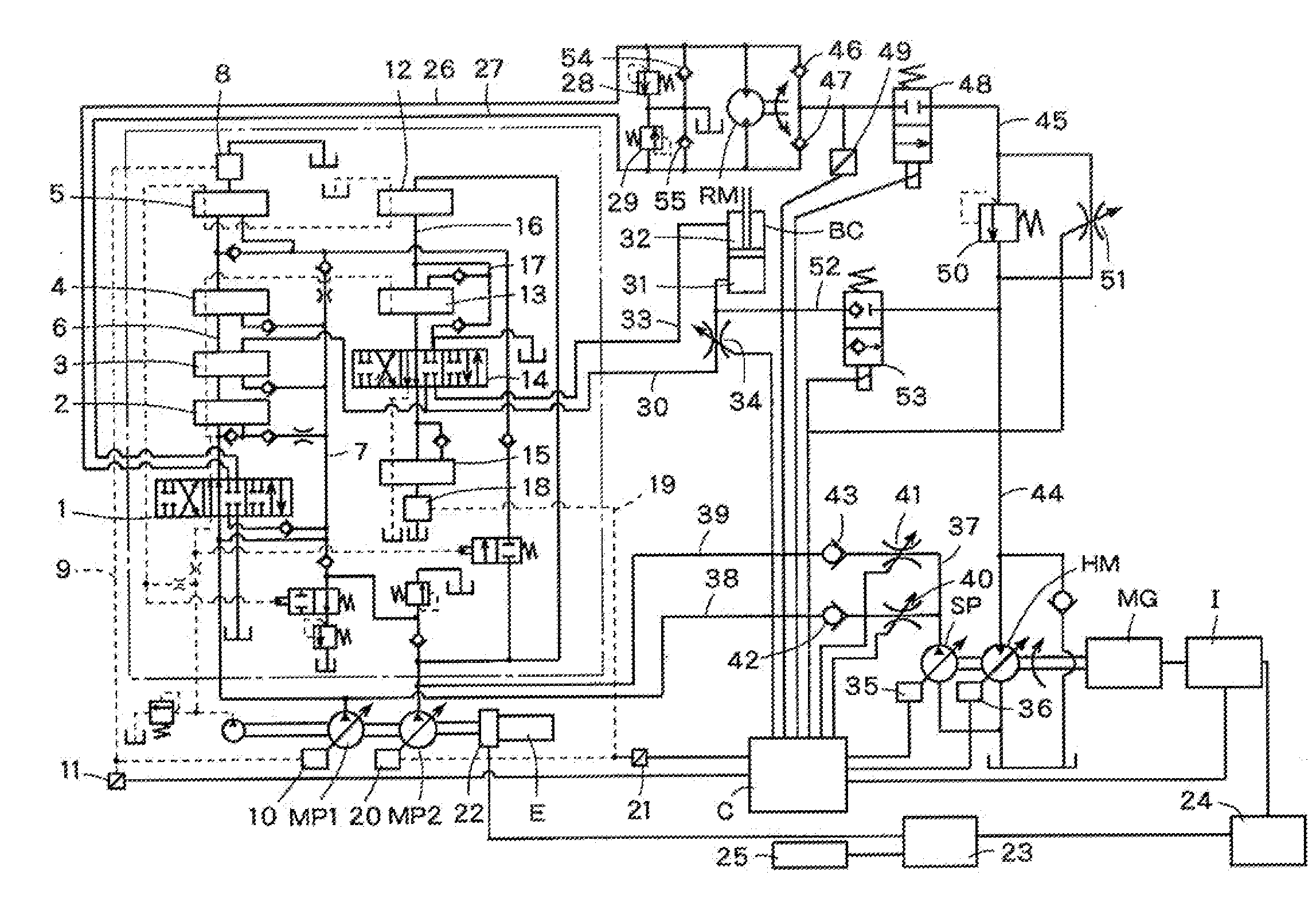
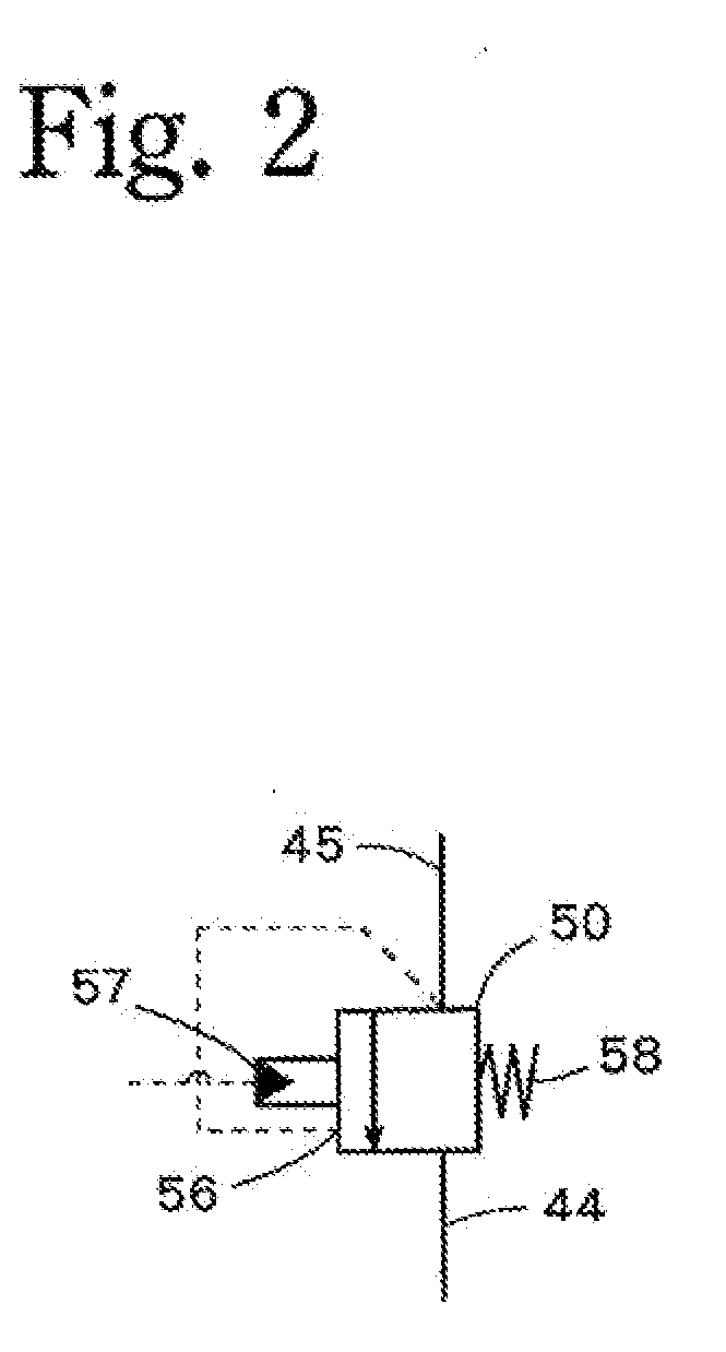
[0125]A fourth embodiment illustrated in FIG. 4 employs a proportional solenoid valve 64 including a combination of the proportional solenoid valve 34 and the solenoid on / off valve 53 which are shown in FIG. 1. The proportional solenoid valve 64 is usually kept in the open position shown in FIG. 4, and upon reception of a signal from the control unit C, the proportional solenoid valve 64 is switched to a right position in FIG. 4. In the proportional solenoid valve 64 switched to the right position in FIG. 4, a throttle 64a is located in the communication process between the boom cylinder BC and the tank T, and a check valve 64b is located between the boom cylinder BC and the hydraulic motor HM. The degree of opening of the throttle 64a is controlled in accordance with the amount of switching of the proportional solenoid valve 64.

[0126]In each of the aforementioned embodiments, the check valves 42, 43 are provided and the solenoid directional control valve 48 and the solenoid on / off ...

first embodiment

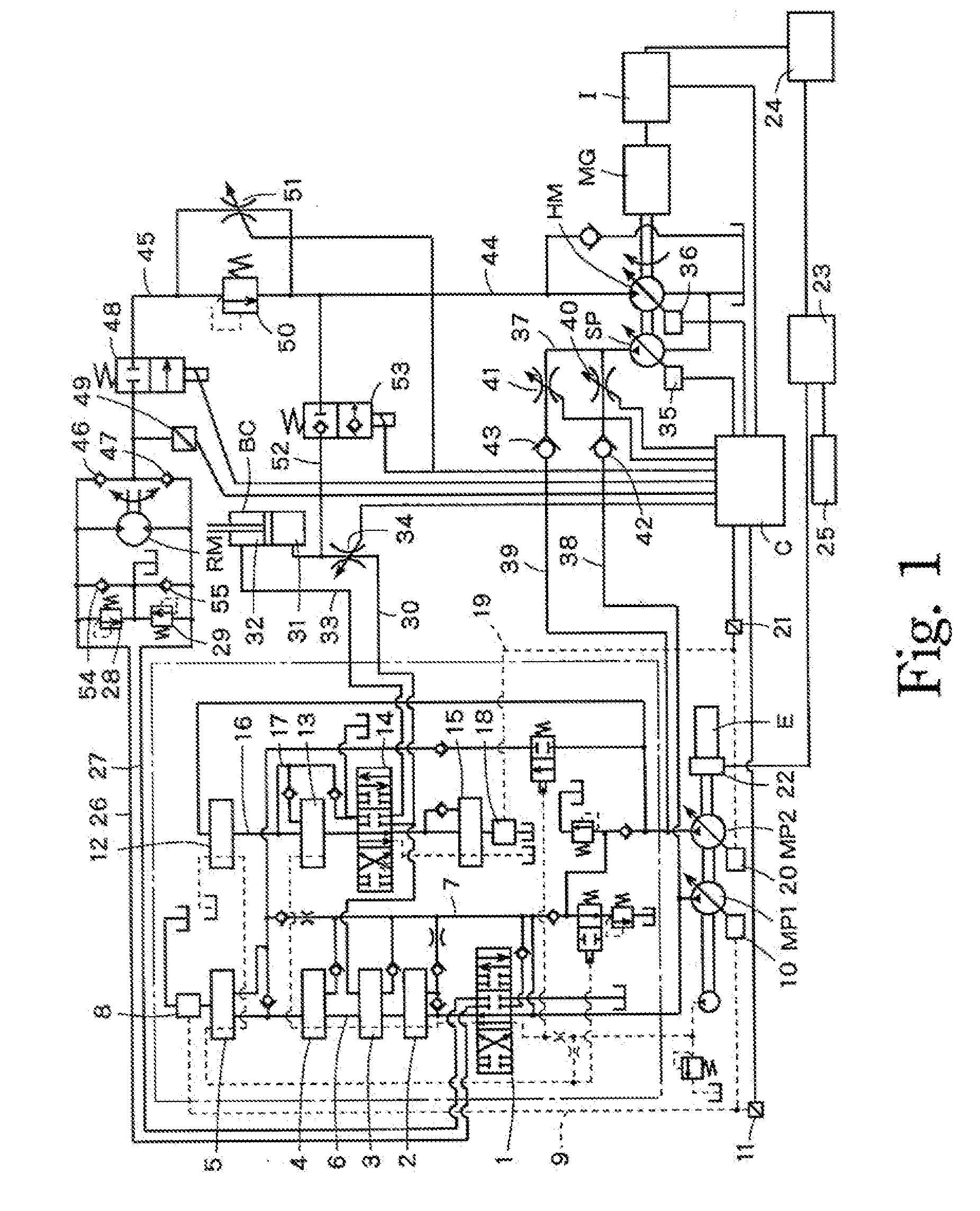
[0128]FIG. 1 is a circuit diagram according to a

second embodiment

[0129]FIG. 2 is a circuit diagram according to a


PUM


Abstract

Effective use of energy is provided by recovering energy produced during braking in operation of a rotation motor RM alone for electric generation. A control unit C has functions: of operating a passage-resistance control unit (51) to reduce the passage resistance by a pressure relief valve 50 when determining based on a detection signal from a neutral-condition detecting unit (6, 8, 9, 11 and 16, 18, 19, 21) that all the operated valves 1-5, 12-15 in the circuit system are in the neutral position and a pressure signal from a brake-pressure-detection processor sensor 49 reaches a preset pressure; of causing a tilt-angle control unit 36 to control the tilt angle of a hydraulic motor HM; and of relatively controlling the passage resistance maintained by controlling the passage resistance control unit and the tilt angle of the hydraulic motor to maintain a brake pressure of the rotation motor.

Description

BACKGROUND OF THE INVENTION[0001]1. Field of the Invention[0002]This invention relates to a controller for controlling a drive source of a construction machine such as, for example, a power shovel and the like, and also controlling energy recovery.[0003]2. Description of the Related Art[0004]Techniques of generating electric power by the use of a return flow from an actuator or the like to rotate a generator have been widely known. One of them recovers energy produced by a rotation motor during braking to rotate a generator.[0005]A hybrid structure in a construction machine such as a power shovel uses, for example, an excess output of an engine to rotate a generator for generation of electric power which is then accumulated in a battery. Then, the power of the battery is used to drive an electric motor in order to actuate an actuator. Also, discharge energy from the actuator is used to rotate the generator for generation of electric power which is similarly then accumulated in the b...

Claims


Application Information

Patent Timeline
IPC IPC(8): G06F19/00F16K31/02
CPCE02F9/2075F15B2211/88E02F9/2235E02F9/226E02F9/2292E02F9/2296F02D29/04F15B11/024F15B21/14F15B2211/40515F15B2211/411F15B2211/41545F15B2211/7051F15B2211/7058F15B2211/7135F15B2211/761F15B2211/763E02F9/2228E02F9/20
Inventor KAWASAKI, HARUHIKOEGAWA, MASAHIRO
Owner KYB CORP
Why Eureka
Try Eureka