

Organic electroluminescence device
a technology of electroluminescence device and material, which is applied in the direction of thermoelectric devices, organic chemistry, platinum organic compounds, etc., can solve the problems of inability to achieve compatibility of performance and performance, low durability of such devices, and difficulty in developing blue phosphorescent materials capable of high efficiency and high durability in a pure blue region of short wavelength
- Summary
- Abstract
- Description
- Claims
- Application Information
AI Technical Summary
Benefits of technology
Problems solved by technology
Method used
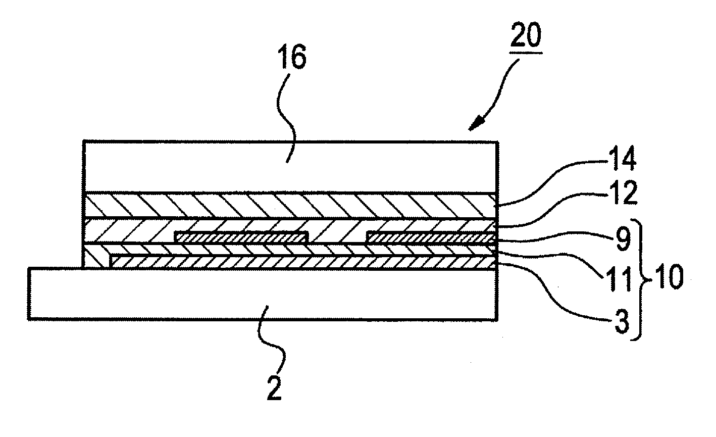
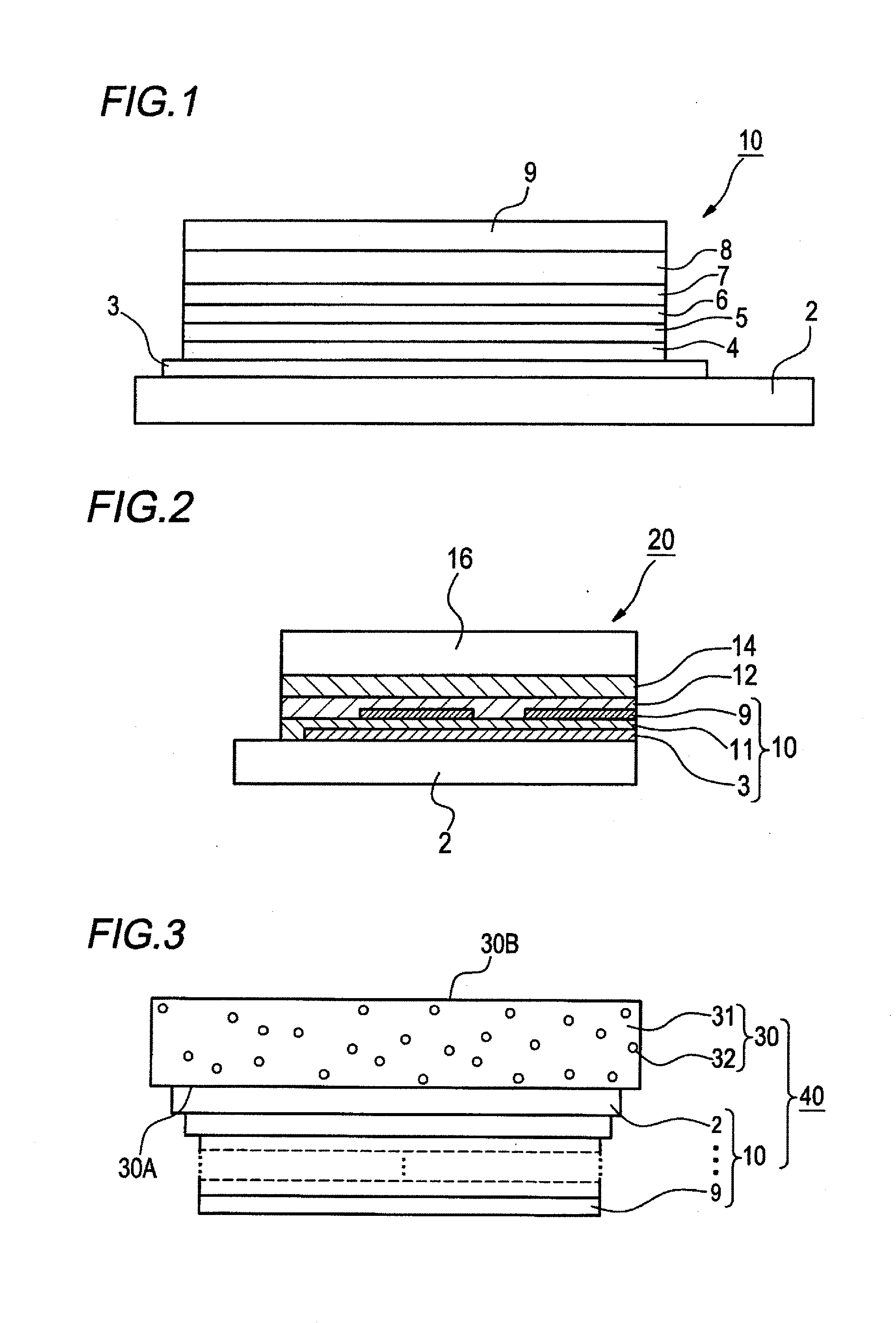
Image

Examples
synthesis example 1
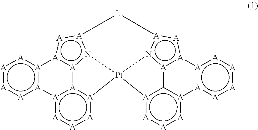
[0243]Exemplified compound G shown below is synthesized.
[0244]Compound a (40.0 mg, 83.9 mmol, 1.0 equivalent), platinum dichloride (23.4 mg, 88.0 mmol, 1.05 equivalents), and silver trifluoroacetate (37.0 mg, 167 mmol, 2.0 equivalents) are stirred in m-tolunitrile (5 mL) for 5 hours and 30 minutes on heating refluxing condition in nitrogen atmosphere. After concentration, drying and solidification of the reaction solution, the obtained residue is offered to silica gel column chromatography (hexane:CH2Cl2:=1:1). The obtained crude product is washed with ethyl acetate / methanol (1 / 2) to obtain 24.0 mg of a platinum complex as yellow powder. Yield: 43%
[0245]1H-NMR (300 MHz, CDCl3) δ: 2.06 (s, 6H), 7.09 (s, 2H), 7.55-7.75 (m, 6H), 8.09 (d, J=7.7 Hz, 2H), 8.18 (dd, J=7.7 Hz, 1.3 Hz, 2H), 8.26 (m, J (Pt—H)=51.2 Hz, 2H), 8.54 (d, J=7.5 Hz, 2H).
Manufacture of Device 1-1 of the Invention:
[0246]A glass substrate having an ITO film (manufactured by Geomatec Co., Ltd., surface resistance: 10Ω / □)...
PUM
| Property | Measurement | Unit |
|---|---|---|
| temperature | aaaaa | aaaaa |
| temperature | aaaaa | aaaaa |
| temperature | aaaaa | aaaaa |
Abstract
Description
Claims
Application Information