Spintronic device and information transmitting method
a technology of information transmission and spintronic device, which is applied in the direction of digital storage, instruments, galvano-magnetic material selection, etc., can solve the problems of joule heat and higher power consumption
- Summary
- Abstract
- Description
- Claims
- Application Information
AI Technical Summary
Benefits of technology
Problems solved by technology
Method used
Image
Examples
first embodiment
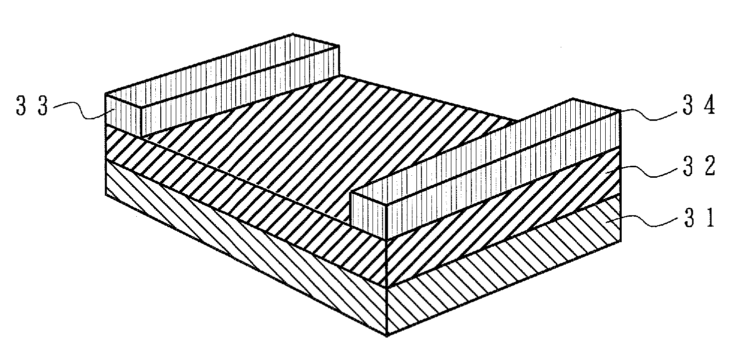
[0076]Next, the spintronic device according to the first embodiment of the present invention is described in reference to FIGS. 12(a) and 12(b). FIG. 12a is a conceptual diagram showing the structure of the spintronic device according to the first embodiment of the present invention, where a YIG layer 32 having a thickness of 50 nm and a Y3Fe4GaO12 composition is formed on a GGG single crystal substrate 31 in accordance with a sputtering method, and a Pt film having a thickness of 10 nm was deposited on top in accordance with a mask sputtering method, so that Pt electrodes 33 and 34 having a width of 1.0 mm were formed with a space of 5.0 mm in between.
[0077]FIG. 12(b) is a diagram illustrating an information transmitting method using a spintronic device where a pulse signal is applied to the Pt electrode 33 so that a pulse current flows through the Pt electrode and a pure pulse spin current is generated in a direction perpendicular to the direction of the pulse current due to the s...
second embodiment
[0081]Next, the spintronic device according to the second embodiment of the present invention is described in reference to FIG. 13. FIG. 13 is a conceptual diagram showing the structure of the spintronic device according to the second embodiment of the present invention, where an antiferromagnetic PdPtMn layer 35 having a thickness of 100 nm is deposited on top of a GGG single crystal substrate 31 in accordance with a sputtering method. A magnetic field is applied to the sample in the direction of the width when the antiferromagnetic PdPtMn layer 35 is deposited.
[0082]Next, a YIG layer 32 having a thickness of 50 nm and a Y3Fe4GaO12 composition is formed on top of the antiferromagnetic PdPtMn layer 35 in accordance with a sputtering method, and a Pt film having a thickness of 10 nm is deposited on top in accordance with a mask sputtering method, so that Pt electrodes 33 and 34 having a width of 1.0 mm are formed with a space of 5.0 mm in between.
[0083]In this case, all of the grains...
PUM
 Abstract
Description
Claims
Application Information
 - R&D
- Intellectual Property
- Life Sciences
- Materials
- Tech Scout
- Unparalleled Data Quality
- Higher Quality Content
- 60% Fewer Hallucinations
Browse by: Latest US Patents, China's latest patents, Technical Efficacy Thesaurus, Application Domain, Technology Topic, Popular Technical Reports.
© 2025 PatSnap. All rights reserved.Legal|Privacy policy|Modern Slavery Act Transparency Statement|Sitemap|About US| Contact US: help@patsnap.com


