Lubricious microfludic flow path system

a flow path and microfluidic technology, applied in the field of flow cytometers, can solve the problems of reducing the purity of collected populations, the flow rate, and the yield of analysis

Inactive Publication Date: 2011-03-31
INGURAN LLC +1
View PDF40 Cites 46 Cited by
  • Summary
  • Abstract
  • Description
  • Claims
  • Application Information

AI Technical Summary

Benefits of technology

[0016]Accordingly, a broad object of the invention can be to provide a lubricious microfluidic flow path system having a lubricious layer coupled to all or a part of the microfluidic conduits. Certain embodiments of the lubricious microfluidic flow path system provide in whole or in part microfluidic conduits having a lubricious layer which as compared to substantially identical conventional conduits allow an increase in the flow rate of a fluid stream in a microfluidic conduit without a corresponding increase pressure of the fluid stream, a decrease in pressure of the fluid stream without a corresponding decrease in the flow rate of the fluid stream, a decrease in the internal diameter of a microfluidic conduit without reduction in the flow rate of the fluid stream at a constant pressure, or the like.

Problems solved by technology

Although co-incidence is a “positive qualifier” (meaning it describes the positive attribute of two particles having a high probability of coinciding in the same drop), for the purposes of sorting particles, co-incidence is typically an unwanted event, as it typically contributes to the collection of contaminating particles correspondingly reducing purity of the collected populations of particles.
A substantial problem with increasing purity by increasing centricity of a particle in a fluid stream typically by reduction in the cross sectional area of the fluid stream can be a reduction in the flow rate of the fluid stream at a given pressure which correspondingly reduces yield of the analysis.
Also, reducing the rate at which particles are entrained within the analysis stream to reduce co-incidence further reduces the yield of the analysis.
Accordingly, particle analysis by conventional microfluidic devices, and specifically in the context of flow cytometry, can be substantially limited by the inability to achieve higher flow rates through lesser internal diameter microfluidic conduits.
However, as above discussed, this conventional approach has the disadvantage of increased co-incidence (more than one sperm cell in one droplet formed such droplets either discarded or contributing to a decrease in purity of the collected sperm cell populations).
For the specific case of sperm cells, this is not possible with conventional flow cytometer means, since the higher pressures (and sheer forces) have been shown to damage or impair sperm cells.
In addition, sort rates can be limited by the amount of time necessary for signal transfer and signal analysis.
Both limits as to flow rate and analysis time have created an upper limit as to sort rate.
However, the greater the ID of either of these elements contributes to a greater variation of centricity and higher CV which results in lower purity and lower yield.
Accordingly, increasing diameter of these conduits may not afford a solution to the problem.

Method used


Image

  • Lubricious microfludic flow path system
  • Lubricious microfludic flow path system
  • Lubricious microfludic flow path system

Examples


example 1

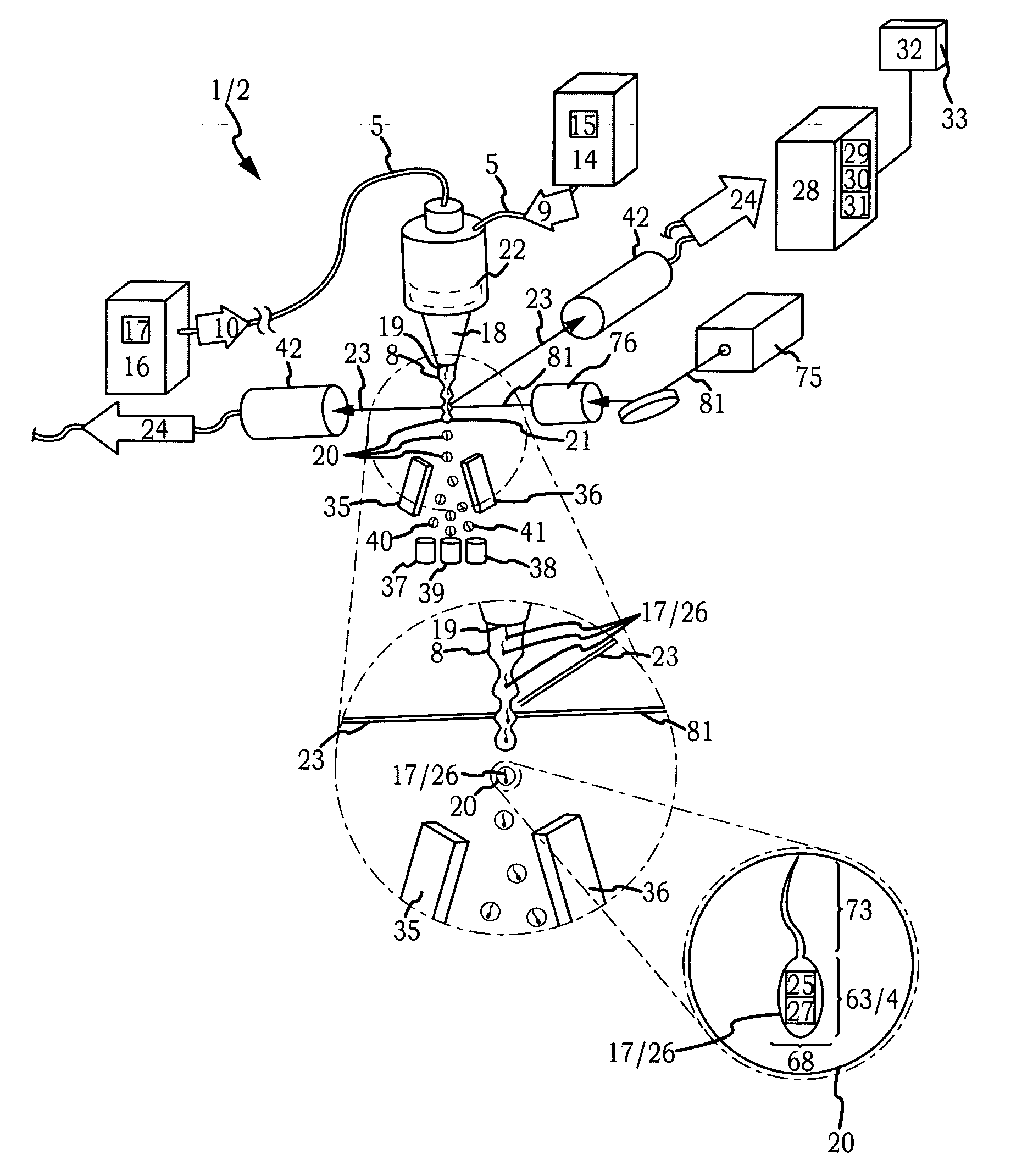
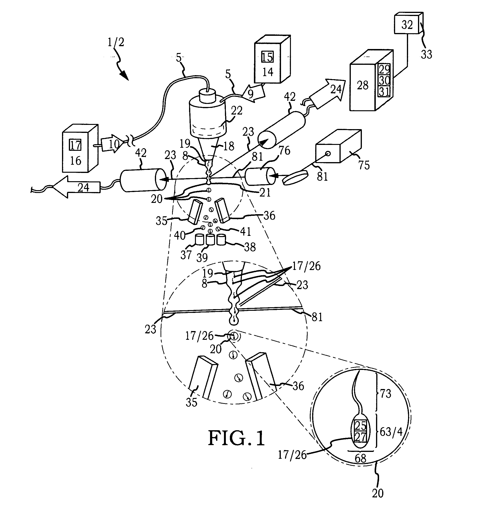
[0094]Modification of Flow Cytometer Nozzle Assemblies and Operation of Flow Cytometers. Four substantially identical conventional nozzle assemblies (43) for a MOFLO® SX flow cytometer manufactured by Beckman Coulter, Fort Collins, Colo. were utilized to provide the standard and experimental nozzle assemblies for comparative trials. A lubricious layer (7) of the hydrophilic polymer poly(vinyl pyrollidone) was applied to the internal substrate surface (6) of the sample fluid conduit (52) and the internal surface of the nozzle (18) of two of the four nozzle assemblies (43). All four of the nozzle assemblies provided a 70 μM diameter nozzle orifice (19). Each of the two standard nozzle assemblies (43) and each of the two experimental nozzle assemblies (43) having the lubricious layer (7) applied as above described were installed onto otherwise substantially identical MOFLO SX® flow cytometers and operated side by side.

Composition of Solutions.

[0095]Sperm Staining Solution: 3 grams / L BS...


PUM

PropertyMeasurementUnit
pressureaaaaaaaaaa
pressureaaaaaaaaaa
velocityaaaaaaaaaa

Abstract

A flow cytometer having a nozzle assembly which provides a lubricious flow path through which a plurality of particles pass to be entrained in a flow of liquid to provide a faster method for sorting with increased cell quality.

Description

I. BACKGROUND[0001]Generally, a lubricious microfluidic flowpath for a particle analysis device. Specifically, a flow cytometer having a nozzle assembly which provides a lubricious flow path through which a plurality of particles pass to be entrained in a flow of liquid.[0002]A number of conventional instruments are available for the separation of a plurality of particles based on differentiable characteristics into two or more populations. Typically, it is desirable to maximize the speed at which the separation based upon the differentiable characteristic(s) occurs, the purity of the isolated population(s) separated based upon the differentiable characteristic(s), and the yield of each of the separated population(s) in number of particles in relation to the total number particles introduced into the separation process.[0003]Typically, it is possible to increase any one of speed, purity or yield; however, this is generally achieved by decreasing the other two. The decrease is most d...

Claims


Application Information

Patent Timeline
Patent Type & Authority Applications(United States)
IPC IPC(8): C12Q1/02C12M1/34
CPCG01N15/1404G01N2015/1406G01N2015/1409G01N2015/149
Inventor GILLIGAN, THOMAS BOYDEVANS, KENNETH MICHAEL
Owner INGURAN LLC
Why Eureka
Try Eureka