Apparatus and method to achieve high-resolution microscopy with non-diffracting or refracting radiation

Active Publication Date: 2011-04-07
UT BATTELLE LLC
View PDF3 Cites 16 Cited by
  • Summary
  • Abstract
  • Description
  • Claims
  • Application Information

AI Technical Summary

Problems solved by technology

Where generation of radiation of sufficient intensity is a challenge, imaging devices employing such radiation tend to suffer from poor spatial resolution.
Otherwise, the diffractive properties of the radiation is insignificant and unobservable, and the radiation does not “substantially diffract,” i.e., the radiation is considered a non-diffracting radiation.
Since imaging efficiency has a direct impact on resolution of images, difficulty in obtaining high radiation intensity from various non-diffracting or refracting radiation sources limits resolution of images obtained using such radiation sources.
Particularly, biomedical imaging devices employing such a radiation source of insufficient intensity generate a low resolution image of a patient.
For exa

Method used


Image

  • Apparatus and method to achieve high-resolution microscopy with non-diffracting or refracting radiation
  • Apparatus and method to achieve high-resolution microscopy with non-diffracting or refracting radiation
  • Apparatus and method to achieve high-resolution microscopy with non-diffracting or refracting radiation

Examples


Embodiment Construction

[0054]As stated above, the present invention relates to an imaging apparatus, a method of operating the same, and a program to perform the operation of the same. The present invention is now described in detail with accompanying figures. It is noted that like and corresponding elements mentioned herein and illustrated in the drawings are referred to by like reference numerals.

[0055]The present invention is described employing neutron radiation. However, the imaging apparatus of the present invention can be employed for any other type of non-diffracting radiation or refracting radiation including, but not limited to, X-ray, gamma ray, ultraviolet radiation, light in the visible spectral range (400 nm-800 nm wavelength), protons, alpha particles, electrons, charged ions, and neutral particles.

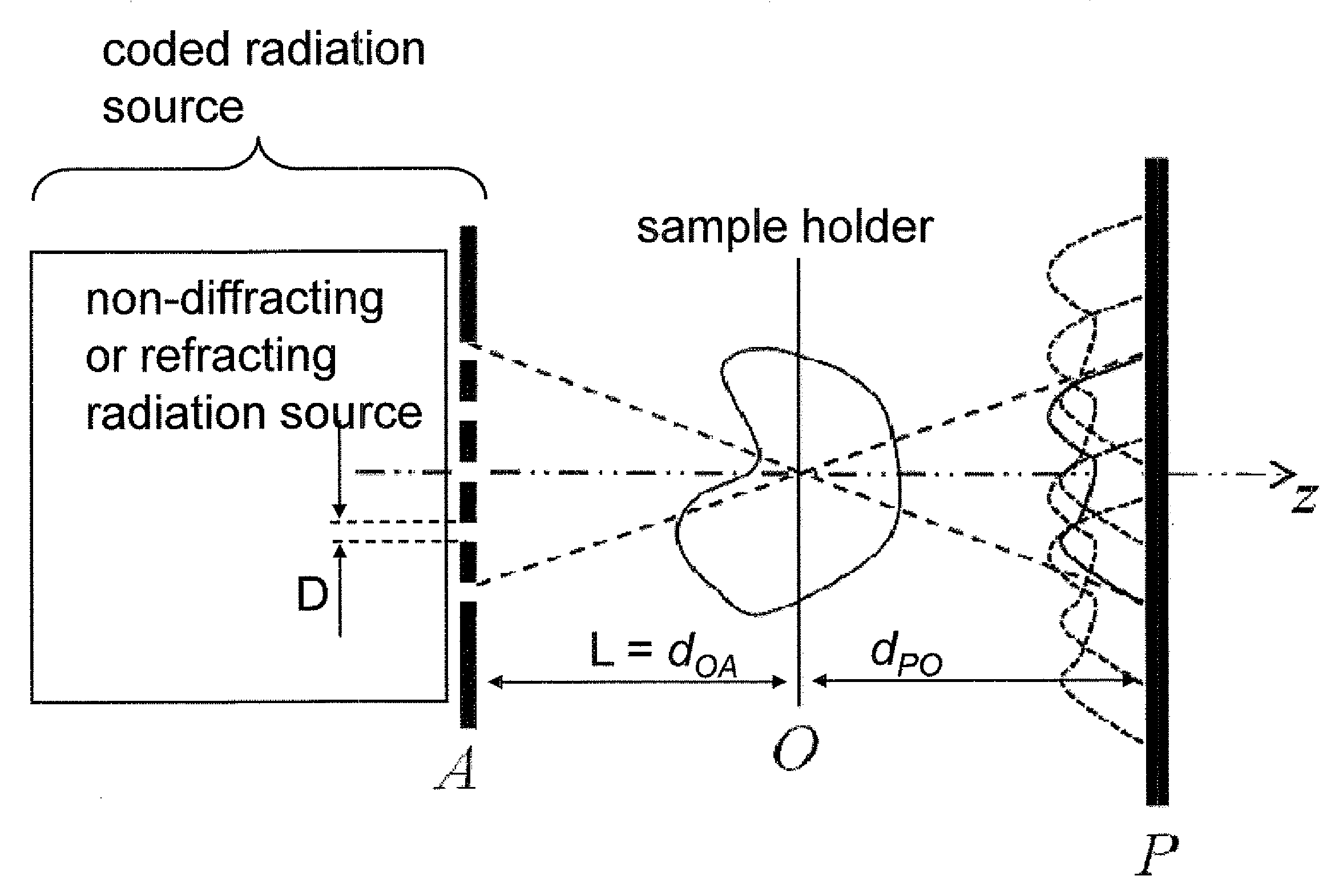
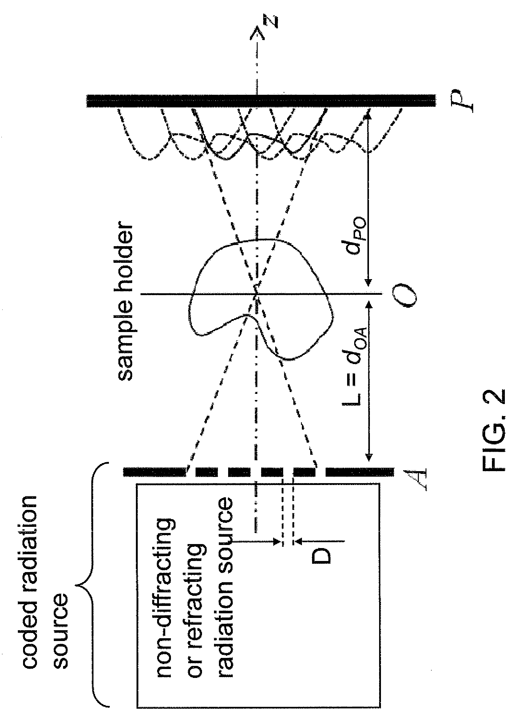
[0056]Referring to FIG. 2, a schematic diagram illustrates the geometry of the imaging apparatus of the present invention. The imaging apparatus employs a “coded radiation source” that includes a...


PUM


Abstract

An imaging system employing a coded aperture mask having multiple pinholes is provided. The coded aperture mask is placed at a radiation source to pass the radiation through. The radiation impinges on, and passes through an object, which alters the radiation by absorption and/or scattering. Upon passing through the object, the radiation is detected at a detector plane to form an encoded image, which includes information on the absorption and/or scattering caused by the material and structural attributes of the object. The encoded image is decoded to provide a reconstructed image of the object. Because the coded aperture mask includes multiple pinholes, the radiation intensity is greater than a comparable system employing a single pinhole, thereby enabling a higher resolution. Further, the decoding of the encoded image can be performed to generate multiple images of the object at different distances from the detector plane. Methods and programs for operating the imaging system are also disclosed.

Description

STATEMENT REGARDING FEDERALLY SPONSORED RESEARCH OR DEVELOPMENT[0001]This invention was made with United States government support under Prime Contract No. DE-AC05-00OR22725 awarded by the U.S. Department of Energy. The United States government has certain rights in this invention.FIELD OF THE INVENTION[0002]The present invention relates to the field of imaging devices employing non-diffracting or refracting radiation, a method of operating the same, and a program to perform the operation of the same.BACKGROUND OF THE INVENTION[0003]Typical imaging systems employ the principles for a single pinhole-style camera. Referring to FIG. 1A, a schematic diagram illustrating the geometry of a conventional pinhole camera is shown. Such a conventional pinhole camera is configured for imaging of an object O emitting or reflecting radiation. In other words, the object O is the source of the emitting or reflecting radiation. The radiation is collected through the pinhole in the aperture mask A, a...

Claims


Application Information

Patent Timeline
IPC IPC(8): G01T1/161
CPCG01T1/295
Inventor TOBIN, JR., KENNETH W.BINGHAM, PHILIP R.HAWARI, AYMAN I.
Owner UT BATTELLE LLC
Why Eureka
Try Eureka