Cutting balloon assembly and method of manufacturing thereof

a technology of which is applied in the field of medical devices, can solve the problems of partial or even complete blockage of the artery, device stiffness, and device equipped with cutting edge or blade, and achieve the effects of improving dilatation and treatment of fibrotic lesions, being more flexible and safer, and being more convenient to us

Inactive Publication Date: 2011-04-07
NORDSON CORP
View PDF21 Cites 61 Cited by
  • Summary
  • Abstract
  • Description
  • Claims
  • Application Information

AI Technical Summary

Benefits of technology

[0013]There is a need in the art to provide a cutting balloon assembly that will be more flexible, safer and provide improved dilatation and treatment of fibrotic lesions.

Problems solved by technology

This can result in a partial, or even complete, blockage of the artery.
One of the drawbacks of the prior art cutting balloons equipped with cutting edges or blades is associated with the fact that these devices tend to be fairly stiff.
This has the affect of limiting the flexibility and deliverability of the balloon as it is advanced through the tortuous confines of a vessel or other body lumens.
Moreover, the cutting balloons equipped with cutting blades and edges can be difficult to deflate and collapse.
This can make removal of the balloons from the vasculature more difficult than the removal of corresponding angioplasty balloons which do not include stiff cutting blades.
Additionally, it was found that the cuts imparted by such cutting balloons do not always provide the dilatation and treatment of fibrotic lesions as would be desired.
An incomplete apposition between the stent filaments and the arterial wall can increase the risk of an embolic source as a result of the stagnation of the blood flow in the dead space.
A strong compression of the vessel wall on the opposite side of the unattachment at the stent edge because of the straightening effect on tortuous vascular curves may induce a kink in the artery that thus could possibly cause edge restenosis.
It is also recognized in the art that incomplete expansion of the stent as compared with a predefined reference (stent underexpansion) can result in calcification, which significantly increases the subsequent risks of restenosis and / or stent thrombosis.

Method used


Image

  • Cutting balloon assembly and method of manufacturing thereof
  • Cutting balloon assembly and method of manufacturing thereof
  • Cutting balloon assembly and method of manufacturing thereof

Examples


Embodiment Construction

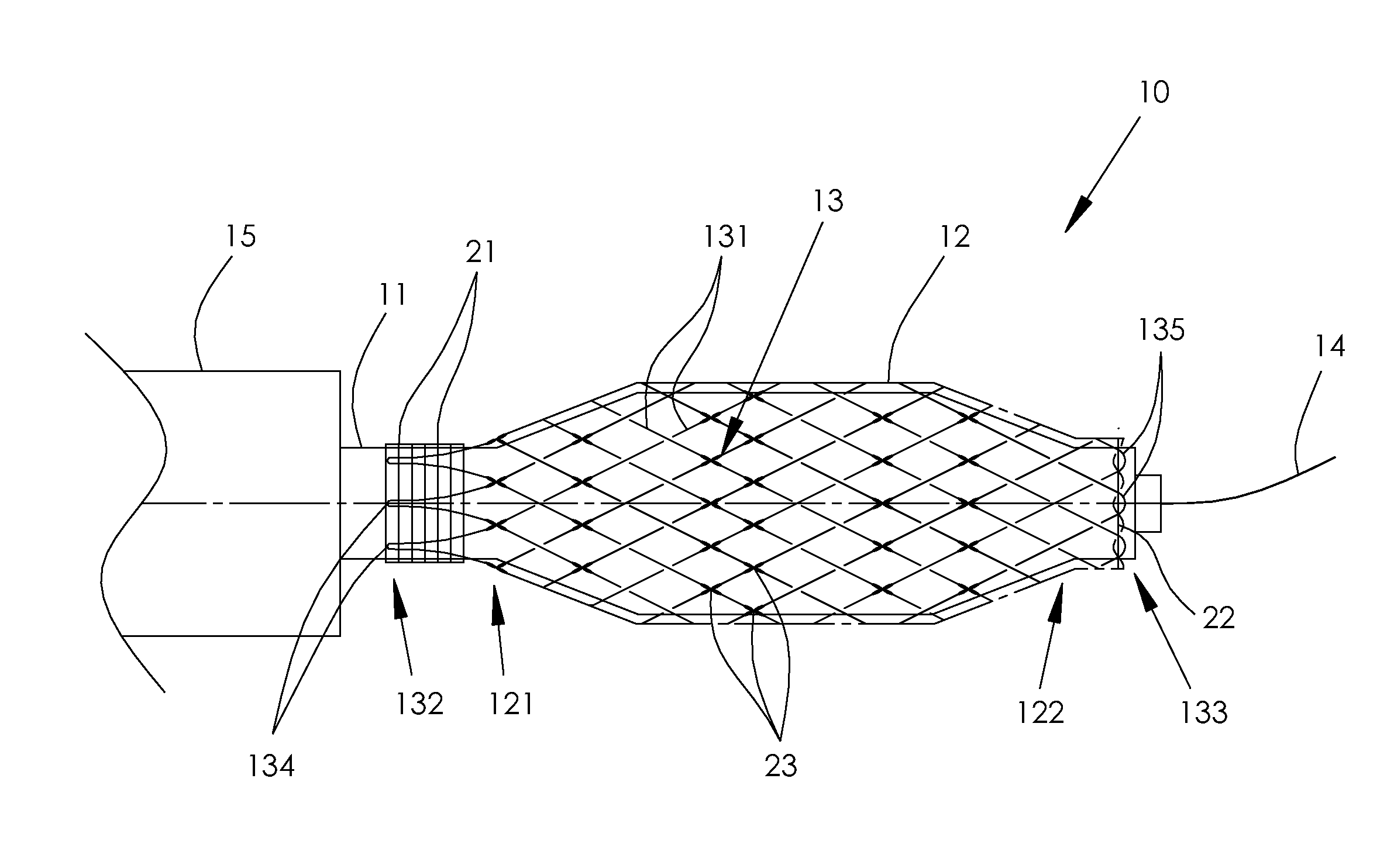
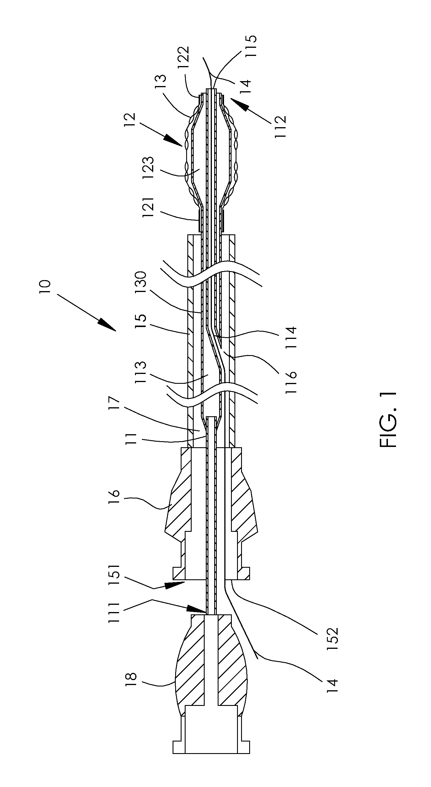
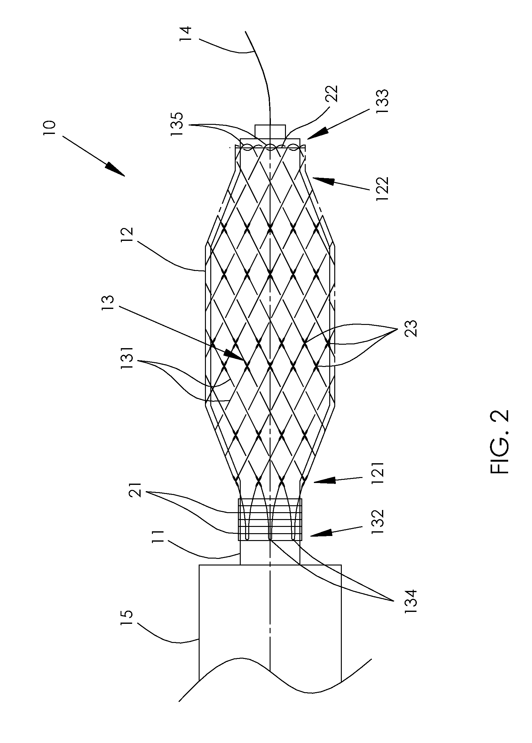
[0049]The principles of the medical device according to the present invention may be better understood with reference to the drawings and the accompanying description, wherein like reference numerals have been used throughout to designate identical elements. It being understood that these drawings which are not necessarily to scale, are given for illustrative purposes only and are not intended to limit the scope of the invention. Examples of constructions, materials, dimensions, and manufacturing processes are provided for selected elements. Those versed in the art should appreciate that many of the examples provided have suitable alternatives which may be utilized. Certain terminology is used herein for convenience only and is not to be taken as a limitation on the present invention. As used throughout this description, proximal and distal orientation relationships are in relation to an operator (e.g., interventional cardiologist / radiologist) utilizing the invention as described he...


PUM

PropertyMeasurementUnit
diameteraaaaaaaaaa
diameteraaaaaaaaaa
diameteraaaaaaaaaa

Abstract

A cutting balloon assembly and a method for fabrication of the assembly is described. The cutting balloon assembly comprises a delivery catheter, an expandable balloon mounted on the catheter distal end, and a scoring mesh disposed around the expandable balloon. The scoring mesh comprises interlacing filaments that extend from a mesh proximal end towards a mesh distal end, form distal filament loops at said mesh distal end, and then return to the mesh proximal end. At least a part of the interlacing filaments forms one or more permanent links with neighboring filaments between the mesh proximal end and the mesh distal end.

Description

FIELD OF THE INVENTION[0001]This invention relates generally to medical devices and more particularly to angioplasty balloon devices for expanding passageways in the venous system.BACKGROUND OF THE INVENTION[0002]One of the most common heart diseases is atherosclerotic cardiovascular disease, caused by the buildup of lesions or plaque on the inside wall of blood vessels. For example, a variety of lesions may occur related to atherosclerosis, including aorto-ostial lesions. Aorto-ostial lesions damage the ostium of the main blood vessels branching from the aorta. This can result in a partial, or even complete, blockage of the artery. As a result of the danger associated with such a blockage, several methods and procedures have been developed to treat arterial blockages.[0003]One such method is an angioplasty procedure which uses an inflatable balloon to dilate the blocked artery. Angioplasty procedure involves the use of a dilatation balloon catheter. The balloon catheter is advanced...

Claims


Application Information

Patent Timeline
Patent Type & Authority Applications(United States)
IPC IPC(8): A61B17/22A61M29/00D03D41/00
CPCA61B17/320725Y10T29/49826A61B2017/00526A61B2017/00539A61B2017/00853A61B2017/00893A61B2017/22061A61F2/958A61M25/0045A61M25/0053A61M25/1034A61M25/104A61M2025/0057A61M2025/105A61B17/22032A61B19/54A61B90/39
Inventor DIAMANT, VALERYDANENBERG, HAIMLOTAN, CHAIMYASKO, NADEZDA
Owner NORDSON CORP
Why Eureka
Try Eureka