Heat-dissipating structure and method for fabricating the same

Inactive Publication Date: 2011-04-14
CHEN YING TUNG +1
9 Cites 24 Cited by

AI-Extracted Technical Summary

Problems solved by technology

Many components used in electronic devices generate considerable heat as an undesirable result of operation that can damage such components (or others) if the heat is not continually removed.
The power consumed by electronic components generally increases with their performance; hence, there is a trend for such components to produce more and more heat, and such high heat is increasingly difficult to effectively remove.
As a result, such heat-generating components are operating closer to their thermal tolerance limit and are thereby more likely to be damaged than ever before.
But this is not the case for many of the newer high-performance CPUs, because such CPUs contain many more transistors and generate more heat, and heat up nearly instantaneously.
Hence, the dense circuitry of a high-performance CPU equipped only with copper heat-dissipating fins is vulnerable.
Although copper is effective in dissipating heat, copper meshes and other devices w...

Benefits of technology

Unlike the prior art, the present invention provides a heat-dissipating structure and a method for fabricating the same such that a plurality of metal particles and carbon particles are coupled to each other by sintering to thereby form a carbon composite layer. According to the present invention, the carbon particles are conducive to enhancement of heat transfer and heat dissipation, and a porosity structure is formed inside the carbon composite layer. The heat-dis...

Abstract

Provided are a heat-dissipating structure and a method for fabricating the same so as for the heat-dissipating structure thus fabricated to dissipate heat from the heat-generating portion of an electronic device. The heat-dissipating structure includes a metal base and a carbon composite layer. The carbon composite layer is formed on the metal base and includes metal particles and carbon particles sintered together. The heat-dissipating structure is more effective in dissipating heat than a conventional vapor chamber or heat spreader. The heat-dissipating structure further includes a carbon composite layer and a metal plate with high thermal conductivity. The heat-dissipating structure is attachable to a heat-generating electronic component to facilitate heat exchange therebetween and thereby enhance heat dissipation.

Application Domain

Technology Topic

Image

  • Heat-dissipating structure and method for fabricating the same
  • Heat-dissipating structure and method for fabricating the same
  • Heat-dissipating structure and method for fabricating the same

Examples

  • Experimental program(8)

Example

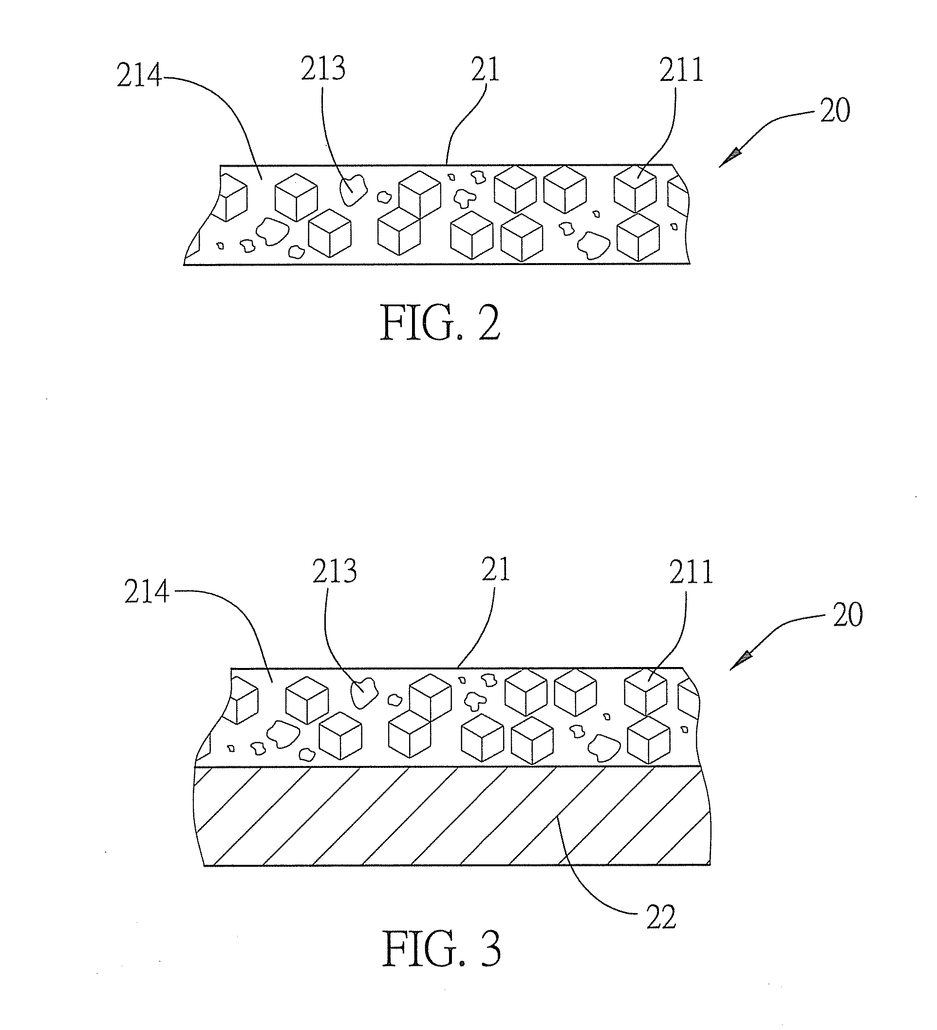
Referring to FIG. 2, a structural cross-sectional view of a first embodiment of a heat-dissipating structure is shown according to the present invention. As shown in the drawing, in the first embodiment of the present invention, a heat-dissipating structure 20 comprises a carbon composite layer 21, the carbon composite layer 21 being formed by mixing and sintering together a plurality of carbon particles 211 and a plurality of metal particles 213.
The carbon particles 211 are of irregular shape. The volumetric ratio of the metal particles 213 to the carbon particles 211 is greater than 1. The diametric ratio of the carbon particles 211 to the metal particles 213 is predetermined. In this embodiment, the volumetric ratio of the metal particles 213 to the carbon particles 211 ranges between 4:1 and 8:1 and is preferably 6:1, and the diametric ratio of the metal particles 213 to the carbon particles 211 is 1:1±15% and preferably 1:1±10%.
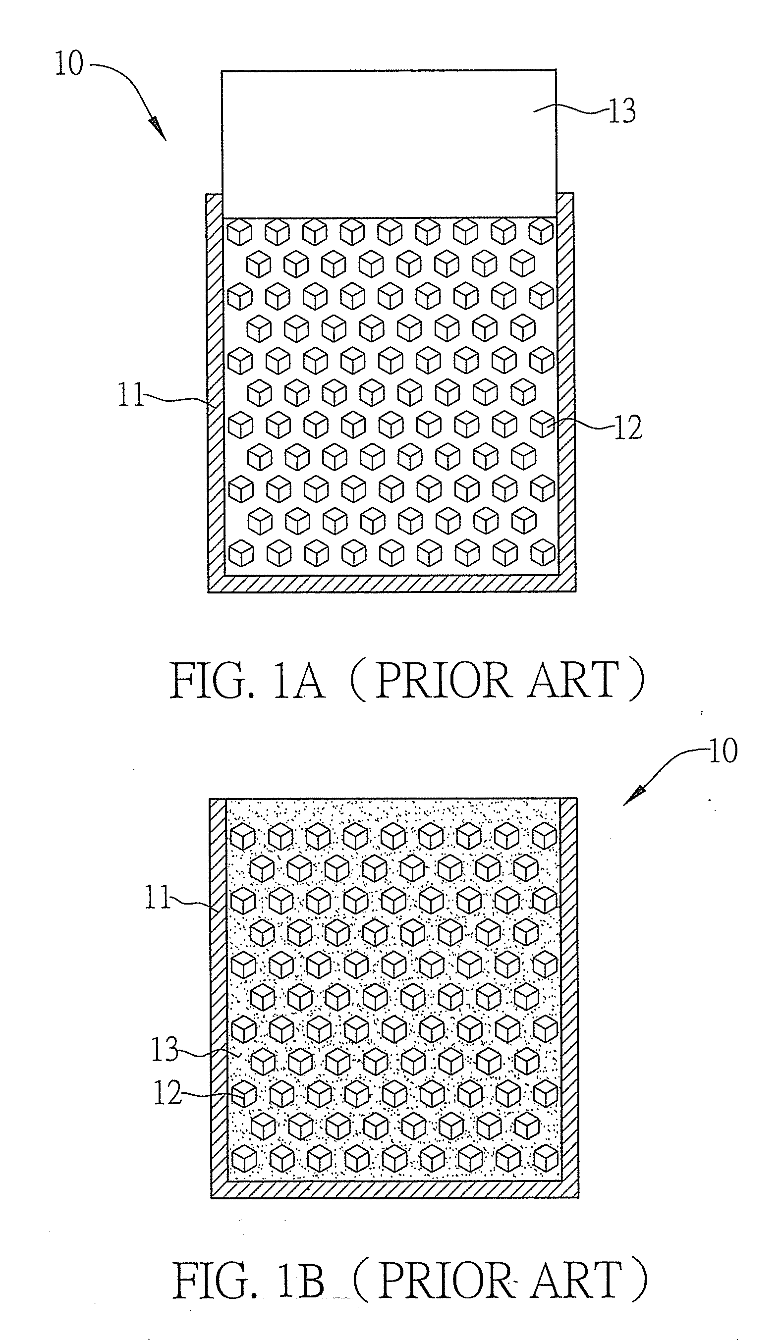
In this embodiment, the sintering of the carbon particles 211 and the metal particles 213 together is achievable by a conventional powder metallurgy process or by a process that combines conventional powder metallurgy with metal injection molding. The process involves mixing the carbon particles 211 with a polymer binder, heating the mixture of the carbon particles 211 and the polymer binder until the mixture becomes as fluid as plastic, shaping the fluid mixture into components of intricate shape by an injection molding machine, debindering a green tape resulting from injection molding to remove the polymer binder, and sintering the debindered green tape to obtain high-density sintered components of satisfactory mechanical and physical properties. Owing to their irregular shape, the carbon particles211 have a relatively large surface area that gives a relatively great porosity to the carbon particles 211 after the sintering thereof. The relatively great porosity of the carbon particles 211 is conducive to heat dissipation. The irregular shape of the metal particles 213 enables the metal particles 213 to be engaged with each other when sintered. Fusion of the metal particles 213 and the carbon particles 211 seldom takes place. It is only when the volumetric ratio of the metal particles 213 to the carbon particles 211 ranges between 4:1 and 8:1 that the metal particles 213 outnumber the carbon particles 211 by a margin wide enough for the metal particles 213 to have a tight grip on the carbon particles 211, such that the metal particles 213 and the carbon particles 211 can be sintered together and engaged with each other. Where the volumetric ratio of the metal particles 213 to the carbon particles 211 is 6:1, the metal particles 213 and the carbon particles 211 are sintered together to exhibit the highest degree of structural strength (thus minimizing loss of said carbon particles 211 during processing) and optimize heat dissipation. As mentioned earlier, the predetermined diametric ratio of the metal particles 213 to the carbon particles 211 is 1:1±15% and preferably 1:1±10%, which is necessary because the carbon particles 211 differ from the metal particles 213 in specific gravity and surface area. Narrowing down the difference in diameter between the carbon particles 211 and the metal particles 213 in a predetermined manner prevents segregation of otherwise separable said metal particles 213 and carbon particles 211.

Example

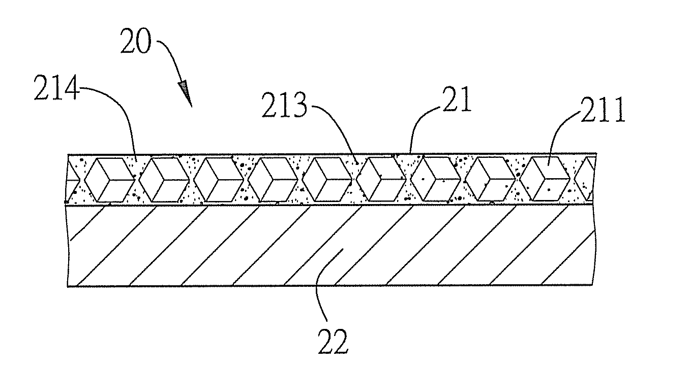
FIG. 3 depicts a structural cross-sectional view of a second embodiment of the heat-dissipating structure according to the present invention. As shown in the drawing, the heat-dissipating structure 20 comprises a metal base 22 and the carbon composite layer 21. The metal base 22 is made of metal of high thermal conductivity, such as copper, aluminum, or nickel. The carbon composite layer 21 is formed by sintering a plurality of metal particles 213 and a plurality of carbon particles 211 together. The sintering of the metal particles 213 and carbon particles 211 causes the surfaces and edges of the metal particles 213 and carbon particles 211 to melt; hence, not only are the metal particles 213 and the carbon particles 211 coupled together, but a porosity structure 214 is provided between the metal particles 213 and the carbon particles 211. In this embodiment, the carbon particles 211 are diamonds, and the metal particles 213 are made of copper, aluminum, silver, or nickel. In this embodiment, the carbon particles 211 are exemplified by industrial diamonds and the metal particles 213 by copper.
Industrial diamonds and copper have thermal conductivity as high as 2300 W/m. K and 401 W/m. K, respectively, that is, much higher than that of other metals. Hence, the present invention provides a heat-dissipating structure made of composite materials of high thermal conductivity that has high thermal conduction. The diameter of the carbon particles 211 ranges between 1 μm and 2 mm, preferably between 50 μm and 180 μm, and more preferably between 90 μm and 110 μm.

Example

FIG. 4 depicts a structural cross-sectional view of a third embodiment of the heat-dissipating structure according to the present invention. As shown in the drawing, in the third embodiment of the present invention, the heat-dissipating structure 20 also comprises a metal base 22 and a carbon composite layer 21. Unlike the first and second embodiments, in the third embodiment, the carbon composite layer 21, which is still formed by sintering a plurality of carbon particles 211 and a plurality of metal particles 213 together, appears in the form of a single layer coupled to the metal base 22. Nonetheless, in other embodiments, the carbon composite layer 21 coupled to the metal base 22 can be either bilayered or multilayered, and sintered together. The heat-dissipating structure 20 features enhanced heat dissipation and enhanced applicability, and the structure can replace conventional heat-dissipating graphite platelets for the following reasons: the uniform size of the carbon particles 211 of the carbon composite layer 21; the high and omni-directional thermal conductivity of the carbon particles 211; and the large surface area of the carbon particles 211.
FIG. 5 depicts a structural cross-sectional view of an operating mechanism for a heat-dissipating structure according to the present invention. As shown in the drawing, to apply the heat-dissipating structure 20 of the present invention, heat-dissipating fins 30 may be disposed above the heat-dissipating structure 20. The heat-dissipating fins 30 are attached to the metal base 22 from above, so as to enhance heat dissipation. Of course, in other embodiments, it is feasible to replace the heat-dissipating fins 30 with a condenser or any other equivalent device. In this embodiment, the metal base 22 is positioned above a heat-generating source, and the heat-generating source is a central processing unit 40 in an electronic device or any other heat-generating assembly. This embodiment is exemplified by the central processing unit 40. The central processing unit 40 generates high heat during operation and thus raises the temperature. The heat-dissipating structure 20 of the present invention is disposed immediately above the central processing unit 40 to thereby enhance heat dissipation.
To use the heat-dissipating structure 20 of the present invention, it is feasible to form inside the metal base 22 (and carbon composite layer 21) a chamber 220 such that the chamber 220 is a partial vacuum and hermetically sealed. The chamber 220 contains a superconductor-dielectric 221. The superconductor-dielectric 221 is usually deionized water or alcohol. Heat generated by the central processing unit 40 during operation is passed by the metal base 22 to the carbon composite layer 21. Upon its rapid absorption by the carbon composite layer 21, the heat is transferred to the superconductor-dielectric 221. The superconductor-dielectric 221 undergoes liquid-phase vaporization to thereby produce high-temperature steam 222. The high-temperature steam 222 thus produced fills the chamber 220 completely. The high-temperature steam 222 condenses as soon as the high-temperature water steam 222 comes into contact with a cool condensation region 223. Condensation enables heat to be transferred to the metal base 22 and the heat-dissipating fins 30 via the carbon composite layer 21 and ultimately released to the ambient environment. A liquid-phase fluid 224 produced as a result of condensation returns to the bottom (above the heat-generating source) by means of the capillarity of the porosity structure 214 of the carbon composite layer 21. The above cycle continually repeats and thereby effectuates quick, efficient heat dissipation.

PUM

no PUM

Description & Claims & Application Information

We can also present the details of the Description, Claims and Application information to help users get a comprehensive understanding of the technical details of the patent, such as background art, summary of invention, brief description of drawings, description of embodiments, and other original content. On the other hand, users can also determine the specific scope of protection of the technology through the list of claims; as well as understand the changes in the life cycle of the technology with the presentation of the patent timeline. Login to view more.

Similar technology patents

Plasmon generator including a main body and a front protrusion

ActiveUS9472230B1Enhance heat dissipationAccurately controlManufacture head surfaceHeads using thin filmsEngineeringMechanical engineering
Owner:HEADWAY TECH INC

Electrical connector

Owner:FOXCONN (KUNSHAN) COMPUTER CONNECTOR CO LTD +1

Spotlight apparatus and manufacturing method thereof

ActiveUS20190056071A1Increase heat dissipationEnhance heat dissipationElectric circuit arrangementsLighting heating/cooling arrangementsLead plateEngineering
Owner:LEEDARSON AMERICA INC

Lighting panel

Owner:DESIGN LED PRODS

Classification and recommendation of technical efficacy words

  • Enhance heat dissipation
  • Enhance heat transfer

Filter box with resonator and reservoir

InactiveUS20050279319A1Enhance heat dissipationUnnecessary power use be avoidNon-fuel substance addition to fuelExhaust apparatusAutomotive engineeringResonator
Owner:MANN HUMMEL GMBH

Plasmon generator including a main body and a front protrusion

ActiveUS9472230B1Enhance heat dissipationAccurately controlManufacture head surfaceHeads using thin filmsEngineeringMechanical engineering
Owner:HEADWAY TECH INC

Pneumatic Tire

ActiveUS20090032161A1Enhance heat transferWorsen heat dissipationInflatable tyresTyre measurementsEngineeringMechanical engineering
Owner:BRIDGESTONE CORP +1

MODULAR REFRIGERATOR and ICEMAKER

InactiveUS20120047917A1Enhance heat transferIce productionDomestic refrigeratorsIcemakerEvaporator
Owner:RAFALOVICH ALEXANDER

Rotating sleeve engine

InactiveUS6289872B1Minimize frictionEnhance heat transferPiston ringsCombustion enginesLubricationCylinder block
Owner:DARDALIS DIMITRIOS

Integrated cooling system for electronic devices

ActiveUS20060034052A1Enhance heat transferPrinted circuit aspectsCircuit fluid transportElectronic assembliesHeat exchanger
Owner:DELPHI TECH IP LTD

Orientation insensitive multi chamber thermosiphon

InactiveUS20080110599A1Enhance heat transferSemiconductor/solid-state device detailsSolid-state devicesEngineeringThermosiphon
Owner:COOLIT SYSTEMS INC
Why Eureka
Try Eureka