
Portable Analytical System for On-Site Analysis of Fluids

Active Publication Date: 2011-04-14
MICROSAIC SYST
View PDF2 Cites 16 Cited by
  • Summary
  • Abstract
  • Description
  • Claims
  • Application Information

AI Technical Summary

Benefits of technology

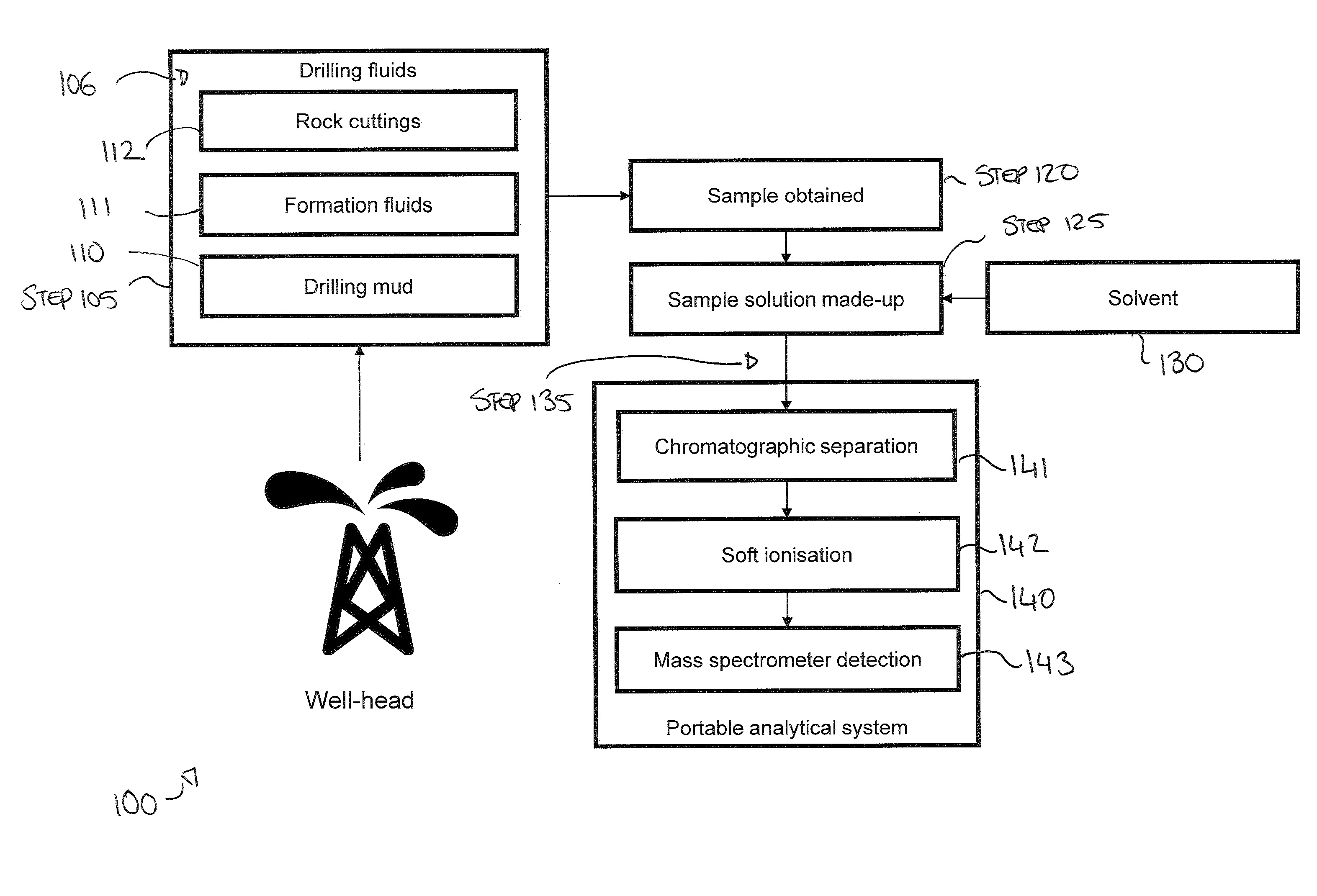
[0009]These and other problems are addressed by the present invention in providing a portable analytical system and a method for using this system for the analysis of samples extracted from drilling fluid. The portable analytical solution may be deployed topside at the well-site and used to perform detailed real-time analysis of formation fluids and extracts of rock cuttings which pass to the surface from a drilling tool. Such a system provides response rates that are sufficiently rapid so as to quickly and effectively separate the chemical constituents from a sample containing drilling fluids or rock cutting extracts, and sufficiently selective so as to permit easy identification of chemical species of interest based on their molecular ions and without the need for spectral interpretation.
[0017]In another embodiment of the invention a portable analytical system is provided, wherein the portable analytical system includes a sample injector, a sample loop, a GC column coupled to an atmospheric pressure ionisation source, an atmospheric pressure vacuum interface and a mass spectrometer detector. In this embodiment of the method a fluid sample is filtered and cleaned-up before being made-up into a solution using a solvent or some combination of solvents. The resulting fluid sample solution is then injected into the injector port, and a sample loop introduces the sample to the GC column. In a preferred embodiment the chromatographic separator is a GC column, but the chromatographic separator may also be a liquid chromatography (LC) system, supercritical fluid chromatography (SFC) system or a capillary electrophoresis (CE) system. The GC column rapidly separates the sample mixture and elutes its components into an atmospheric pressure ionisation source. Atmospheric ionisation sources typically employ soft ionisation techniques that generate a molecular ion permitting easy interpretation of spectra, limiting fragmentation and easing identification of chemical species particularly when more than one compound elutes simultaneously from the chromatographic column. In a preferred embodiment the atmospheric pressure ionisation source is an electrospray ionisation (ESI) source, but atmospheric ionisation sources are not limited to ESI and include nanospray ionisation, APCI, APPI, DART, DESI, Low temperature plasma ionisation (LTP), APGDI, APCDI and SESI. The ions generated by the atmospheric ionisation source are transmitted into the vacuum chamber by an atmospheric pressure interface before being analysed and identified by means of a mass spectrometer detector.

Problems solved by technology

Most of these techniques are too expensive or complicated to implement on every exploration well.
Also, these methods cannot always detect residual oil, particularly if its concentration is beneath the limit of detection (LoD) of the measuring device.
LWD tools and measurements are expensive, and involve adding tools to the drill stem and sending them ‘down-hole’ to measure characteristics like resistivity, pressure, gamma radiation, density, porosity, water saturation and so on.
Testing of this kind is often undertaken before making expensive decisions about well completion.
Typically, GC-MS analysis has been carried out using large, expensive and power hungry instruments located in central laboratories often remote from well-sites.
The turn-around for analysis of drilling mud and cuttings by GC-MS would be of the order of two to four weeks from sample collection to delivery of a report on chemical composition—often too late to have an impact on drilling decisions with a high opportunity cost such as geo-steering, well testing or well completion.
One disadvantage of commercially available well-site GC and GC-MS technology is that it is limited to detecting low carbon number hydrocarbons (e.g. C1 to C5).
Due to their large size, weight and infrastructure overhead it would not be feasible to deploy them at the well-site.

Method used


Image

  • Portable Analytical System for On-Site Analysis of Fluids
  • Portable Analytical System for On-Site Analysis of Fluids
  • Portable Analytical System for On-Site Analysis of Fluids

Examples


Embodiment Construction

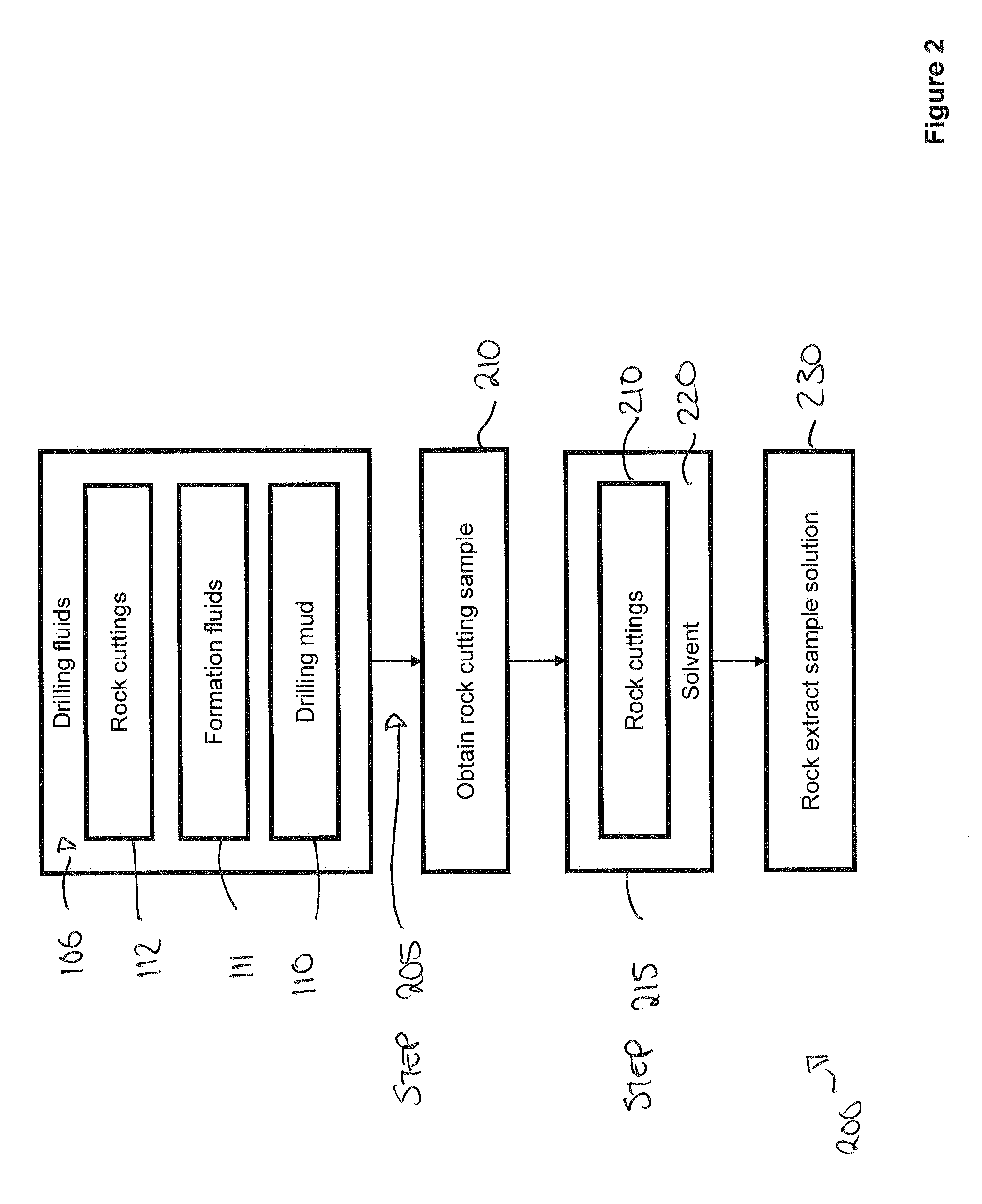
[0029]A detailed description of preferred exemplary embodiments of the invention is provided with reference to FIGS. 1 to 12.

[0030]It will be appreciated that drilling extracts and crude oil are ‘messy’ samples. Due to the complex chemical matrix that is a drilling fluid sample, or a bitumen sample extracted from a drilling cutting, lengthy chromatographic separation times are required to ensure adequate separation and purification of all the compounds in the mixture. Gas chromatographic (GC) retention times of the order of hours may be required before all the components of have eluted from the GC column. In fact, samples of interest may contain tens of thousands of components. While users may not need to separate and identify all of the components during drilling, nonetheless an analytical solution will need to rapidly separate and analyse complex samples and identify their components. In the context of modern-day drilling operations, where drilling speeds of hundreds of metres / fee...


PUM


Abstract

A portable analytical system for the rapid on-site analysis of fluids, and a method for using this system at the well-site for the analysis of samples extracted from drilling fluids is described. The portable analytical solution may be deployed at the well-site and used to perform detailed real-time analysis of formation fluids and extracts of rock cuttings. The method described could be used during hydrocarbon exploration and production to determine whether the drill stem has passed through a hydrocarbon-bearing region, or rocks that are capable of functioning as an oil reservoir or that may have been a source rock, or that may have come into contact with oil, or that may contain oil at present.

Description

CROSS-REFERENCE TO RELATED APPLICATIONS[0001]This application claims the benefit of United Kingdom Patent Application Serial No. 0917758.5 filed on Oct. 12, 2009.TECHNICAL FIELD OF THE INVENTION[0002]The present invention relates to on-site fluid analysis and in particular to a portable analytical system for the rapid on-site analysis of fluids, and a method for using this system ‘topside’ at a well-site for the analysis of samples extracted from drilling fluids. The invention more particularly relates to an apparatus and methodology that may be used in analysis of drilling fluids which have been returned to the surface, or topside, at the well-site location. In such an environment, the portable analytical solution may deployed at the well-site and used to perform detailed real-time analysis of formation fluids and extracts of rock cuttings for use during oil and gas exploration and production to determine whether the drill stem has passed through a hydrocarbon-bearing region, or ro...

Claims


Application Information

Patent Timeline
IPC IPC(8): G01V5/04
CPCH01J49/00G01N33/2823E21B49/08G01N33/0009G01N33/241
Inventor FINLAY, ALAN
Owner MICROSAIC SYST
Learn More