A
loudspeaker represents a sensitive load that regularly operates at or near its rated AC power and presents challenges to the art of AC power protection, clue to the fact that
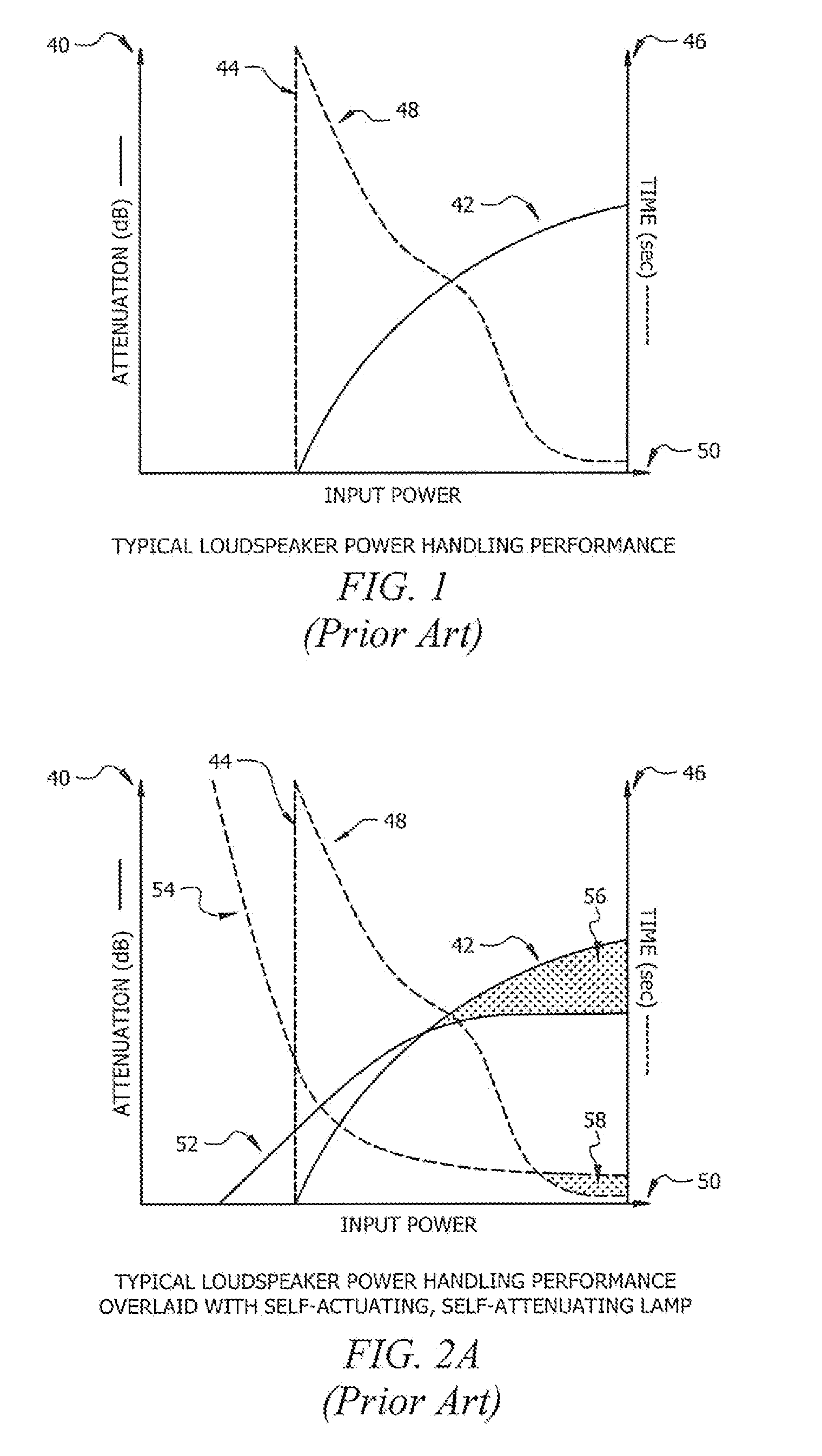
loudspeaker transducers typically can
handle large power levels for a
short duration and reduced power levels for longer durations.
In other words, the
time duration of the overage is critical to monitor for protective purposes; power limiting too soon will not allow full utilization of the
transducer, while power limiting too late will result in permanent damage to the
transducer.
Protecting sensitive loads from excessive AC power can be a difficult task and many existing techniques have failed to adequately protect the load from all overage conditions while allowing permissible voltages and currents to pass unaltered.
Unfortunately, attenuating these high power signals has been costly, inefficient, and resulted in signal degradation.
Furthermore, AC dimmers have not made efforts to incorporate protective monitoring circuitry, leaving the lamp or load unprotected against AC overage conditions.
Unfortunately, self-actuating devices such as TVS diodes, MOVs, thermistors, etc. are not adjustable and actuation thresholds can vary significantly depending on ambient temperature and / or production tolerances.
Unfortunately, lamps also have several deficiencies such as filament damage,
insertion loss, nominal maximum impedance, light output, and excessive
heat generation.
Fuses are relatively inexpensive and somewhat effective; however, they are designed with fixed trip thresholds, they have predetermined response times, and once blown, are permanently destroyed, i.e. they must be physically replaced.
For most sensitive load applications, fuses are not acceptable due to excessive
response time wherein the load may sustain permanent damage.
Specialized
Positive Temperature Coefficient thermistors (PTCs) have been developed to address the permanent destruction issue common to fuses or fusible links, but they fail to solve the fixed threshold and
response time problems.
Controlled actuation is desirable due to the ability to easily change or program the voltage or current thresholds that result in actuation, but many of the electromechanical actuators, such as relays, suffer from limited
response time.
For example, a standard power
relay has a typical turn-on time of approximately five milliseconds, and in some scenarios, this
lag in actuation can result in damage to a sensitive load.
While non-programmable actuation control circuits are effective, they do not allow threshold and
time coefficient adjustment without changing circuit component values (resistors and capacitors).
While resistive attenuation has achieved the desired result, the drawbacks are significant.
Excessive power dissipation requires large, costly resistors, and in some cases specialized heat sinks and / or liquid cooled apparatus are required to dissipate the
thermal energy.
Unfortunately, these existing techniques of continuously attenuating or stepping-down the AC power signal suffer from several significant problems.
Circuitry designed to attenuate an AC power signal using resistive attenuation suffers from excessive
power loss, thereby requiring large, high-power resistive elements that produce significant heat and can be costly.
Alternatively, approaches using the
transformer step-down approach benefit from much lower loss (typically 1-2 dB
insertion loss), but introduce the following drawbacks to the
system: (1) significant physical size and weight due to
low frequency magnetic core, (2)
frequency response degradation (low frequencies are rolled off), (3) costly as power increases, (4)
transformer core saturation problems limit the effective usefulness to low power applications (typically 100 W or less), (5) fixed number of secondary windings “taps” (typically 4) does not allow fine
amplitude control.
These problems have been prevalent for decades, and no improved solution has been established in situations where continuous attenuation is required.
Unfortunately, the lamps attenuation plateaus and is significantly less than what the load requires to maintain damage-free operation.
This initial excessive speed will clamp many safe transient power levels quicker than required.
Lamps also have a nominal impedance even when they are not actuated or lighting, which results in a measurable
insertion loss.
Finally, lamps have a maximum
power rating at which the filament can be damaged upon over-powering the device, which greatly limits the operational power range of circuits that incorporate lamps without subsequent filament protection.
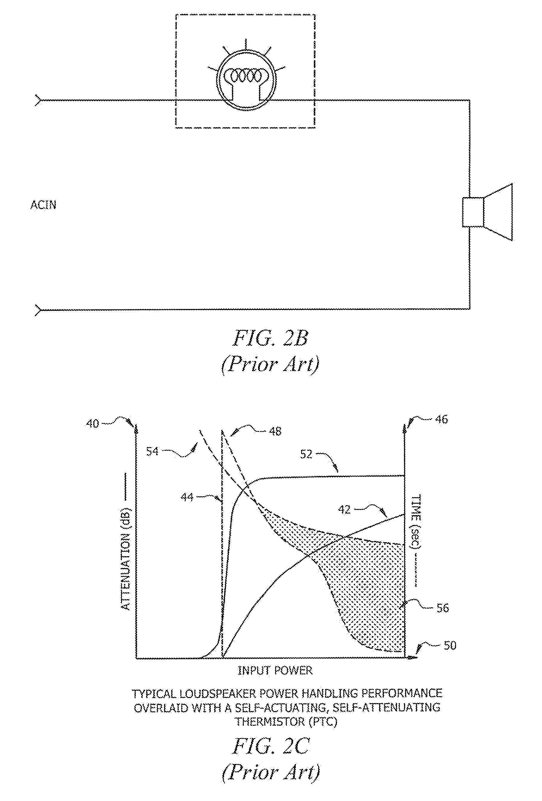
While the PTC does offer adequate attenuation, the fast-acting step attenuation response is not optimal, and when used for
loudspeaker protection is easily detected by the
human ear.
Unfortunately, while selecting smaller PTC devices will speed the
time response, the actuation threshold is typically much less than the desired
power rating of the load.
Additionally, PTC devices will remain actuated with a small amount of
trickle current, leading to poor release and
recovery performance.
PTC actuation thresholds will also vary greatly depending upon the ambient temperature, greatly limiting the effective operational temperature range of circuits incorporating such devices.
Because of these problems, designers have great difficulty finding a single PTC device that meets all of the desired requirements with respect to time, attenuation, actuation thresholds, and release performance.
Unfortunately, the inadequate attenuation of the lamp at
higher power levels remains a problem and allows operation in the damage region, 56.
This initial excessive speed will clamp many safe transient power levels quicker than required.
The overall result for a non-
time delayed relay circuit is a less than optimal protection topology for dynamic sensitive loads such as loudspeakers.
Additionally, typical
relay designs have suffered from actuation chatter wherein the relay actuates and releases rapidly when the input signal is crossing the relay coil threshold.
Such chatter degrades the life of the relay contacts significantly.
However, there remains a small region of damage susceptibility, 58, wherein the actuation
lag is not fast enough to protect the loudspeaker from large transients.
These devices, while very fast, have presented several problems to high-performance protection circuits: (1) excessive currents exist when clamping and can result in damage to the clamping device, the AC source, or passive line conditioning circuitry connected thereto; (2) clamping techniques result in non-linear loading on the AC driving device and are not acceptable for protection circuits that are required to connect to a variety of different AC sources; and (3) significant signal
distortion is added when voltage clamping, or “clipping”, is active.
Due to these significant problems with clamping and crow-bar designs, no effort was made to present graphical plots of their performance.
Therefore, it should be stressed that the lack of digitally programmable attenuation and
microprocessor based control were two fundamental deficiencies of prior art in AC power protection of sensitive loads.
In summary, existing AC power protection circuits have suffered from the following problems: non-programmable attenuation, lossy attenuators generating excessive heat and / or light output, non-programmable thresholds and timing coefficients, high
insertion loss, abrupt stepped actuation, non-linear loading, inadequate peak voltage and current protection, limited operational power range, and actuation chatter.
Additionally, existing circuits designed for continuous AC attenuation have suffered from excessive power dissipation (heat), cost, limited control,
magnetic core saturation problems,
frequency response anomalies, and no over-power protection monitoring.

