Low NOx Combustor for Hydrogen-Containing Fuel and its Operation

a nox combustor and hydrogen-containing technology, which is applied in the ignition of turbine/propulsion engines, engine starters, lighting and heating apparatus, etc., can solve the problems of insufficient reduction of nox emission and likely damage to burners, and achieve the effect of suppressing nox emission

Active Publication Date: 2011-04-28
MITSUBISHI POWER LTD
View PDF8 Cites 28 Cited by
  • Summary
  • Abstract
  • Description
  • Claims
  • Application Information

AI Technical Summary

Benefits of technology

[0011]The present invention provides the combustor that ensures reliability for a hydr...

Problems solved by technology

However, the burner located at a head portion of the combustor is a premixed combustion burner that burns fuel under a fuel lean condition.
When a hydrogen-containing gas, which has a high burning velocity, is used for the premixed combustion burner, since a flame is formed too close to the burner, the burner will probably be ...

Method used


Image

  • Low NOx Combustor for Hydrogen-Containing Fuel and its Operation
  • Low NOx Combustor for Hydrogen-Containing Fuel and its Operation
  • Low NOx Combustor for Hydrogen-Containing Fuel and its Operation

Examples


first embodiment

[0034]The first embodiment describes an integrated coal gasification combined cycle (IGCC) plant. FIG. 6 shows the outline configuration of a system of the IGCC plant according to the first embodiment.

(Configuration and System of IGCC Plant)

[0035]As shown in FIG. 6, the IGCC plant according to the present embodiment includes a gasifier 21, a clean-up unit 22, a CO2 capture and storage unit 23, a gas turbine 5, and an air separation unit 11. In the gasifier 21, coal gasification gas 60 is generated by a reaction of coal 20 with oxygen 120. In the clean-up unit 22, impure substances contained in the fuel are removed by desulfurization and dust removal. Thus, the coal gasification gas 60 is cleaned to form clean coal gasification gas 62.

[0036]The clean-up unit 22 supplies the coal gasification gas 62 to the CO2 capture and storage unit 23 through one of the systems from an outlet of the clean-up unit 22, and supplies the coal gasification gas 62 from which CO2 is not collected, to the ...

second embodiment

[0090]The first embodiment describes the example of the IGCC plant. The second embodiment describes an example of an operation of a power plant that uses COG as fuel. The COG is generated when coke is formed in a steel plant.

[0091]FIG. 10 is an outline diagram showing a system of the plant according to the second embodiment. In the plant according to the present embodiment, COG 161 generated in a coke oven 24 is cleaned by a clean-up unit 25. After that, the COG 161 is mixed with blast furnace gas (BFG 163) generated in a blast furnace so that the calorific value of the fuel is controlled. The mixture is used as fuel for a heat source 24a for dry distillation included in the coke oven 24. Linzer donawitz gas (LDG) generated in a converter furnace is stored in a gas holder (not shown). After that, the LDG is used as fuel for a boiler 29.

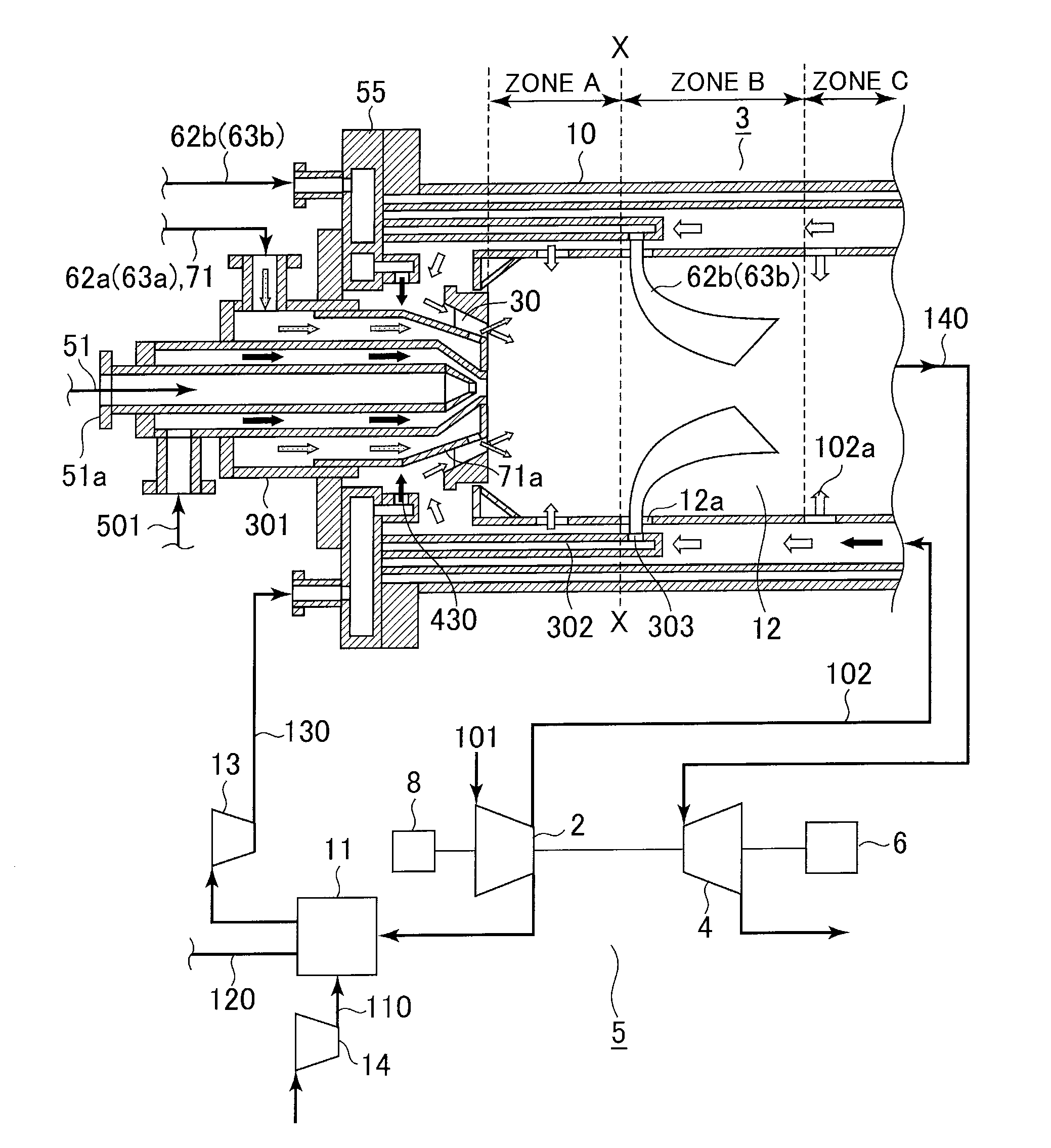
[0092]FIG. 7 is an enlarged cross sectional view of a system of a gas turbine and a combustor. The combustor shown in FIG. 7 is similar to the combus...

third embodiment

[0100]The third embodiment describes an example of an operation of a power plant that uses, as fuel, an off gas generated in an oil refinery plant.

[0101]FIG. 13 shows an outline configuration of the plant according to the present embodiment. In the plant according to the present embodiment, a precise distillation unit 31 separates oil 50 by distillation into naphtha or the like. In addition, a resolution unit 32 develops the naphtha into various petrochemical products. A reforming unit 33 reforms generated gas. Off gas containing hydrogen is generated in each of the distillation unit 31, the resolution unit 32, and the reforming unit 33.

[0102]In the plant according to the present embodiment, the raw off gas is temporarily stored in a gas holder 34. A clean-up unit 35 performs desulfurization and the like on the gas. Chemical species containing three or more carbon atoms are extracted as liquefied propane gas (LPG) 263. Remaining hydrogen containing gas 262 is used as fuel for the ga...


PUM


Abstract

An object of the present invention is to provide a gas turbine combustor that supports hydrogen-containing gas having a high burning velocity and is capable of performing low NOx combustion without reducing reliability of a burner. A first fuel nozzle is provided upstream of a combustion chamber and supplies fuel for activation and hydrogen-containing gas. The combustor has a primary combustion zone, a reduction zone and a secondary combustion zone. In the primary combustion zone, the fuel supplied from the first fuel nozzle is combusted under a fuel rich condition to form a burned gas containing a low concentration of oxygen. In the reduction zone, a hydrogen-containing gas is injected into the combustion chamber through a second fuel injection hole from a second fuel nozzle so that NOx generated in the primary combustion zone is reduced by an oxygen reaction of the hydrogen. In the secondary combustion zone, air for lean combustion is supplied into the combustion chamber so that unburned part of fuel is combusted under a fuel lean condition.

Description

BACKGROUND OF THE INVENTION[0001]1. Field of the Invention[0002]The present invention relates to a combustor that supports an operation with a hydrogen-containing gas, and a method for operating the combustor while suppressing NOx emission.[0003]2. Description of the Related Art[0004]Fuel rich-lean combustion based on a diffusive combustion system is one of methods for suppressing NOx emission while ensuring reliability of a burner. The fuel rich-lean combustion is performed in such a manner that fuel is supplied through a single system. In operation, the fuel is supplied to a primary combustion zone provided at a head portion of the combustor and is then burned (fuel rich combustion) under a fuel rich condition so that an increase in the flame temperature is suppressed, thereby suppressing generation of NOx. Next, unburned fuel from the primary combustion zone flows down into a secondary combustion zone provided downstream of the combustor. Then, the unburned fuel is supplied with ...

Claims


Application Information

Patent Timeline
IPC IPC(8): F02C7/22
CPCF23C2900/9901Y02E20/18F23R3/346
Inventor KOIZUMI, HIROMIDODO, SATOSHITAKAHASHI, HIROKAZUASAI, TOMOHIROKOGANEZAWA, TOMOMIYOSHIDA, SHOHEI
Owner MITSUBISHI POWER LTD
Why Eureka
Try Eureka