Direct digital synthesizer for reference frequency generation

a digital synthesizer and reference frequency technology, applied in the field of frequency synthesizer circuit architectures, can solve the problems of spreading spurious signals, noise-like phase addition, and dithering to the output of delay generators, so as to reduce overall power consumption and lower frequency signals

Inactive Publication Date: 2011-04-28
CYMATICS LAB CORP
View PDF17 Cites 35 Cited by
  • Summary
  • Abstract
  • Description
  • Claims
  • Application Information

AI Technical Summary

Benefits of technology

[0015]In certain preferred embodiments discussed herein, the multi-modulus divider selects between first and second divider ratios, while in other preferred embodiments the multi-modulus divider selects between a first divider ratio, a second divider ratio and a third divider ratio. In some instances selected embodiments also have one or more programmable dividers. In these embodiments, the programmable divider operates on the signal input i

Problems solved by technology

These values introduce a noise-like phase dither to the output of the delay generator.
This noise-like phase

Method used


Image

  • Direct digital synthesizer for reference frequency generation
  • Direct digital synthesizer for reference frequency generation
  • Direct digital synthesizer for reference frequency generation

Examples


Embodiment Construction

[0036]The present invention is described in terms of several embodiments. In describing these embodiments, including the drawings, specific terminology will be used for the sake of clarity. Also, in the discussion of certain mathematical relationships, certain variable values are discussed by way of illustration. However, the invention is not intended to be limited to the specific embodiments described below.

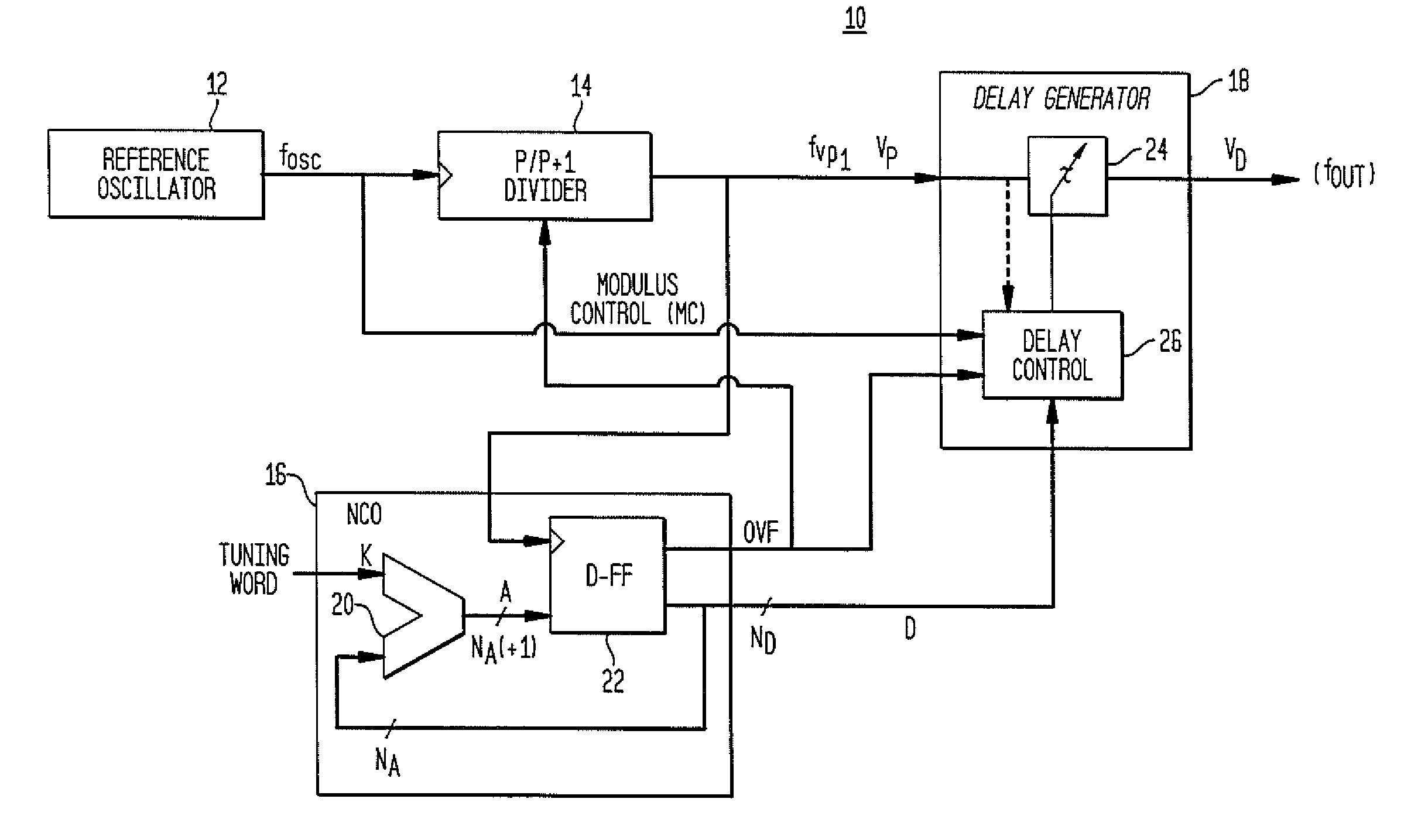
[0037]FIG. 1 is a schematic illustration of a multi-modulus divider direct digital synthesizer (“DDS”) architecture 10 in accordance with aspects of the present invention. This exemplary DDS architecture 10 includes a reference oscillator 12, a multi-modulus divider 14, an NCO 16 and a delay generator 18, which is also referred to herein as a “phase interpolator.”

[0038]Reference oscillator 12 produces a periodic waveform with a frequency fosc. As shown in the figure, fOSC is provided to the multi-modulus divider 14 and the delay generator 18. The reference oscillator 12 may, by ...


PUM


Abstract

A direct digital frequency synthesizer having a multi-modulus divider, a numerically controlled oscillator and a programmable delay generator. The multi-modulus divider receives an input clock having an input pulse frequency fosc and outputs some integer fraction of those pulses at an instantaneous frequency fVp that is some integer fraction (1/P) of the input frequency. The multi-modulus divider selects between at least two ratios of P (1/P or 1/P+1) in response to a signal from the numerically controlled oscillator. The numerically controlled oscillator receives a value which is the accumulator increment (i.e. the number of divided pulse edges) required before an overflow occurs that causes the multi-modulus divider to change divider ratios in response to receiving an overflow signal. The numerically controlled oscillator also outputs both the overflow signal and a delay signal to the delay generator. The delay signal contains phase-dithering noise that is induced by input into the accumulator of an increment generated from a pseudo-random noise generator. The delay signal further controls the frequency of the multi-modulus divider output signal (Vp) to provide an output signal (VD) with an fOUT that has improved phase and timing jitter performance over prior art direct digital frequency synthesizer architectures.

Description

CROSS-REFERENCE TO RELATED APPLICATIONS[0001]The present application is a continuation-in-part application of U.S. patent application Ser. No. 12 / 229,948 filed Aug. 28, 2008, and claims the benefit of U.S. Ser. No. 12 / 229,948, which is to issue as U.S. Pat. No. 7,724,097. The disclosure of Ser. No. 12 / 229,948 application is incorporated by reference herein.BACKGROUND OF THE INVENTION[0002]1. Field of the Invention[0003]The present invention provides frequency synthesizer circuit architectures that are particularly adapted for use in computation, control and communication applications.[0004]2. Description of Related Art[0005]Low frequency (32 KHz-300 MHz) clock or timing signals are employed in electronic devices for many different applications. A typical reference oscillator may use a quartz resonator or another resonator which may operate on a fundamental frequency (less than about 40 MHz) or an overtone mode of oscillation (about 30 to 300 MHz). However, certain electronic devices...

Claims


Application Information

Patent Timeline
IPC IPC(8): H03L7/00
CPCH03L1/027G06F1/025
Inventor TSANGAROPOULOS, ANTHONY L.GUILLOU, DAVID FRANCOIS
Owner CYMATICS LAB CORP
Why Eureka
Try Eureka