Fluorine purification

a technology of fluorine and purification gas, which is applied in the field of purification gas, can solve the problems of high consumption of inert gas, increase the risk of contamination of manufactured products, and low efficiency, and achieve the effects of reducing time, cost, and waste of products

Inactive Publication Date: 2011-04-28
FLUOROMER
View PDF11 Cites 13 Cited by
  • Summary
  • Abstract
  • Description
  • Claims
  • Application Information

AI Technical Summary

Benefits of technology

[0014]Still another aspect of the present disclosure is the continuous operation of an F2 purification apparatus. Continuous operation is preferable for the industrial production and use of F2 because the continuous operation reduces contamination to the apparatus and to the product stream. Continuous operation, additionally, reduces wasted product, time, and expense associated with shutting down and starting up the purification process
[0015]Still another aspect of the p...

Problems solved by technology

The build up of impurities on the walls of semiconductor deposition chambers increases the risk of contamination of the manufactured product.
The most difficult technological task is purifying NF3 that contains a CF4 impurity, since even small amounts of CF4 create a significant problem in the process of etching semiconductors due to the formation of carbon or silicon carbide residues.
The diffi...

Method used


Image

  • Fluorine purification
  • Fluorine purification
  • Fluorine purification

Examples


example

[0078]The following example further illustrates the methods and apparati of the present invention. Those skilled in the art will recognize that modification to the apparati and methods are available and may be different from those represented in the example.

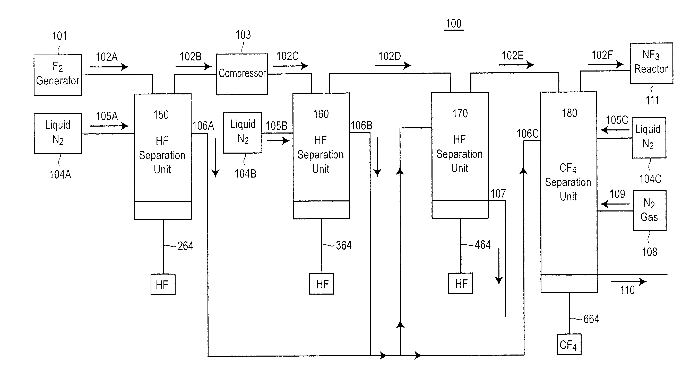
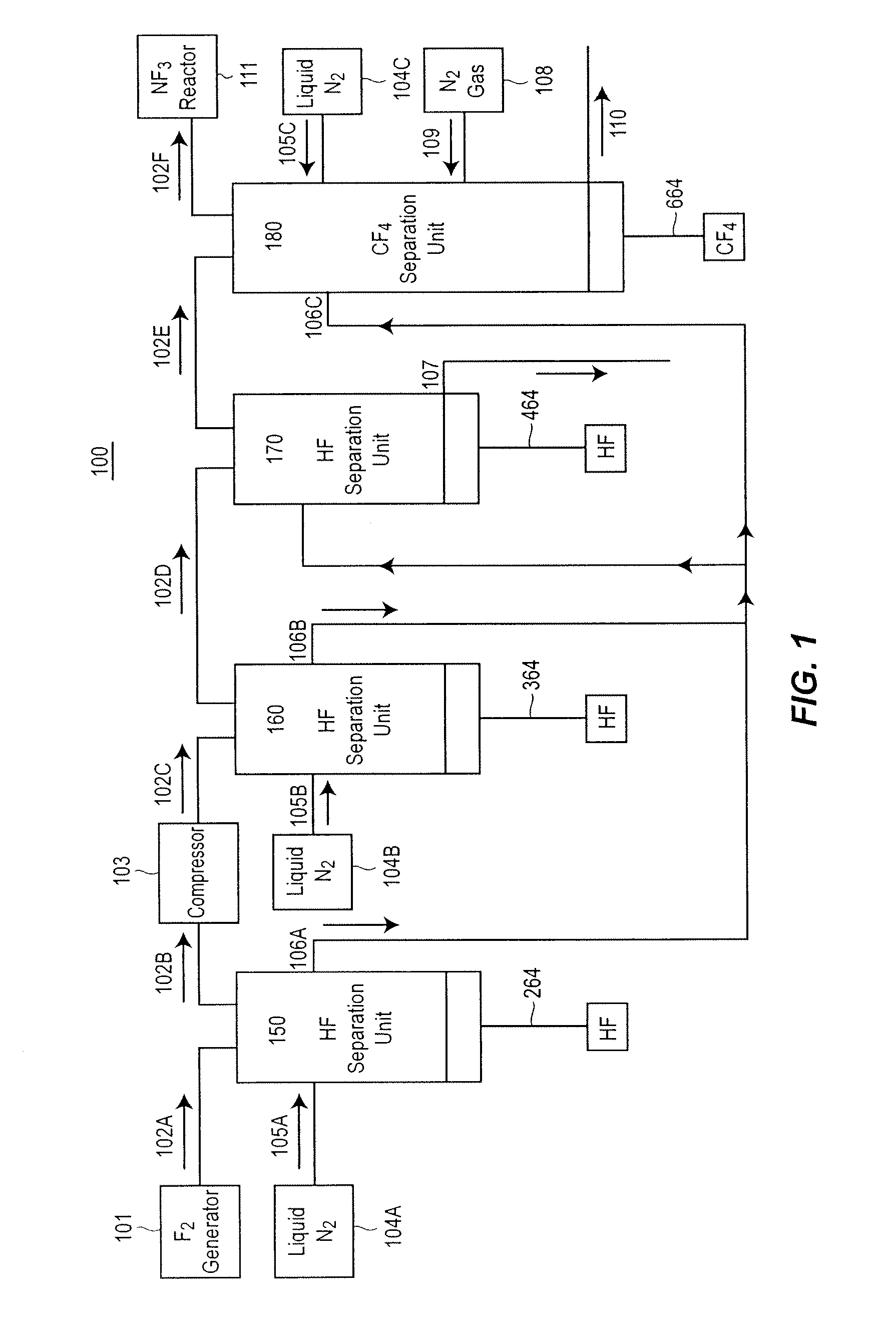
[0079]A Fluorine Purification Apparatus 900 similar to that shown in FIG. 9 was constructed and tested. In the direction of F2 flow from the F2 Generator 901 the apparatus in FIG. 9 has a Low Pressure HF Separation Unit 950, a F2 Compressor 903, a High Pressure HF Separation Unit 960, a plurality or Low Temperature HF Separation Units 970 and a CF4 Separation Unit 980. Reference to the operation of these individual units, the mode and operation of the coolants within these units, and other specifics can be found above in the description of the similarly labeled units and in FIGS. 2-8.

[0080]In this example, the liquid coolants in the Low Pressure HF Separation Unit 950 and the High Pressure HF Separation Unit 960 were CHF3, which ...


PUM


Abstract

A method producing a volume of purified F2 comprising removing HF from a F2 feed and removing CF4 from the F2 feed, wherein a concentration of HF in the volume of purified F2 is less than 1 ppm (v/v) and a concentration CF4 in the volume of purified F2 is less than 10 ppm (v/v).

Description

FIELD OF THE INVENTION[0001]The present disclosure relates to the field of ultra-pure gases. More specifically, the disclosure relates to apparatuses and methods for the production of ultra-pure fluorine and ultra-pure nitrogen trifluoride.BACKGROUND AND PRIOR ART[0002]Elemental fluorine (F2) is extremely reactive combining easily with most organic and inorganic materials. Historically, the largest use of F2 was in the manufacture of uranium hexafluoride for use in the nuclear power industry. Other uses included the production of SF6 for use in electrical and electronic equipment and the production of selective fluorinating agents. Newer uses for F2 include laser applications and as a reactant in semiconductor manufacturing.[0003]F2 is primarily produced by the electrolysis of KF.HF with an anode oxidizing fluoride ions to liberate F2 and a cathode reducing hydrogen ions to liberate H2. Generally, the anode is carbon and the cathode is nickel. The electrolytic process requires a sig...

Claims


Application Information

Patent Timeline
IPC IPC(8): C01B21/06B01D53/00B03C3/01
CPCB01D53/002B01D53/68B01D53/75B01D2256/26B01D2257/2045B01D2258/0216Y02C20/30B03C3/49B03C9/00B03C11/00C01B7/195C01B7/20C01B21/0835B03C3/017Y02P20/151
Inventor IIKUBO, YUICHIOWENS, STEPHEN
Owner FLUOROMER
Why Eureka
Try Eureka