Method for preparing graphene ribbons where structure is controlled

a graphene ribbon and structure technology, applied in the direction of nano-carbon, specific nanostructure formation, material nanotechnology, etc., can solve the problems of inability to fabricate graphene ribbons with zigzag (or armchair) configurations, low yield of graphene via chemical routes, and low yield of graphene for mass production, etc., to achieve simple and better physical properties.

Inactive Publication Date: 2011-04-28
KOREA INST OF SCI & TECH
View PDF0 Cites 48 Cited by
  • Summary
  • Abstract
  • Description
  • Claims
  • Application Information

AI Technical Summary

Benefits of technology

[0011]According to the present invention, graphene ribbons having better physical properties than commercialized carbon nanotubes can be fabricated in a simple manner and in a great quantity. The graphen

Problems solved by technology

However, this method has a problem that the yield is very low.
However, the yield of graphene via chemical routes, which has been proposed for mass production, may be also very low because the ratio of residues in the centrifuged supernatan

Method used


Image

  • Method for preparing graphene ribbons where structure is controlled
  • Method for preparing graphene ribbons where structure is controlled
  • Method for preparing graphene ribbons where structure is controlled

Examples


example 1

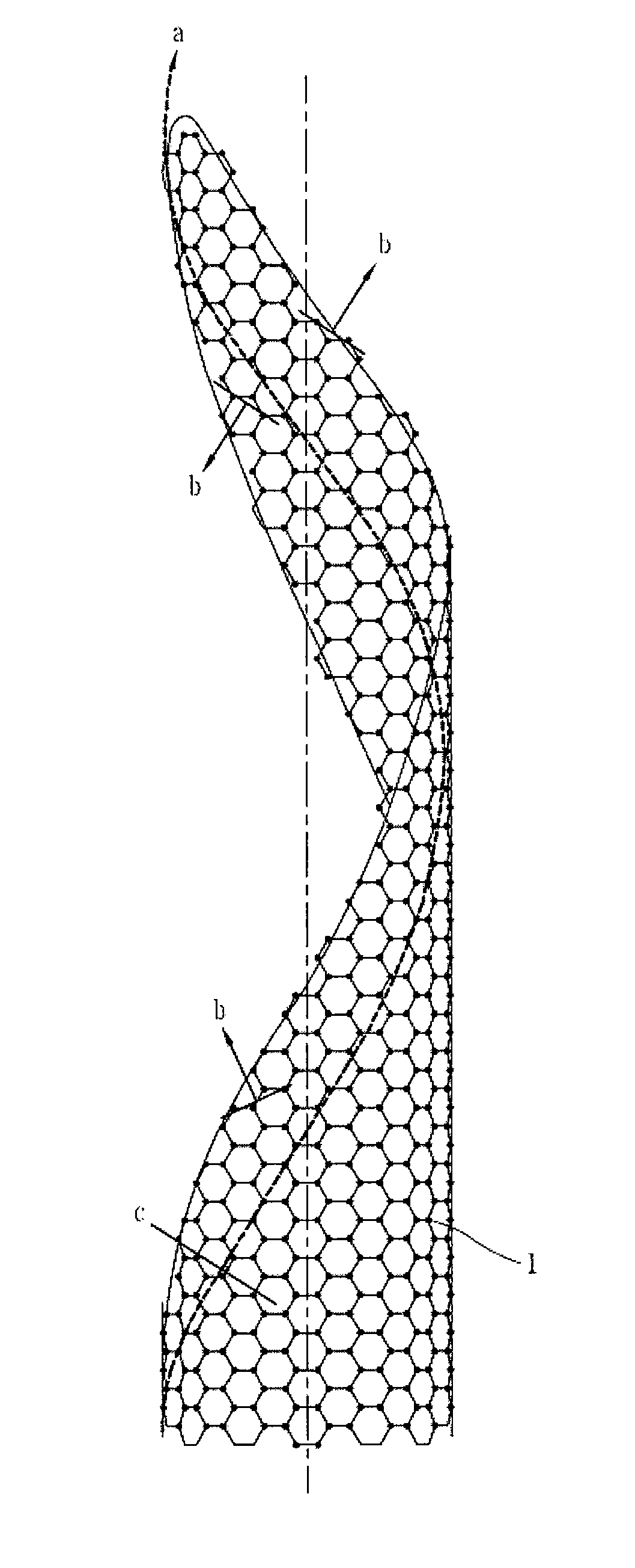
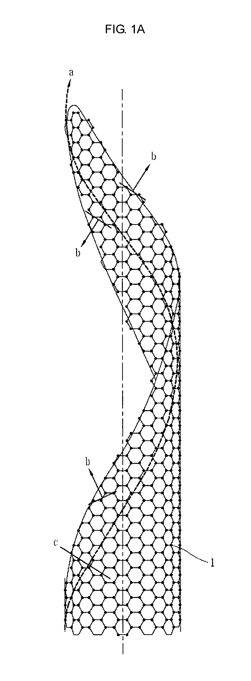
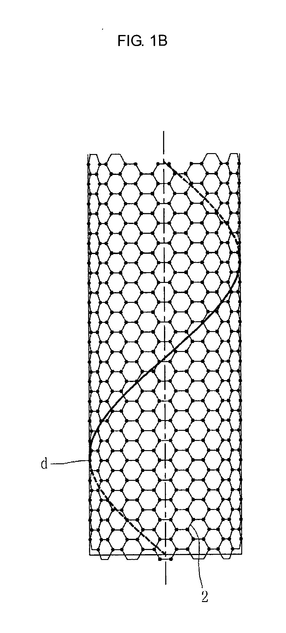
[0038]Graphene ribbons were fabricated by using a carbon structure (raw material) in which graphene ribbons having a zigzag configuration fabricated in the chemical vapour deposition (CVD) process had been spirally grown to form a tube shape. The carbon structure, which is a raw material, was 1-4 nm in diameter, and 1 μm in length. The carbon structure, which is a raw material, was treated in an ultrasonic device (power 500 W). The transformation ratio based on the ultrasonic treatment condition is illustrated in Table 1. The solution used for ultrasonic treatment was alcohol. As a result of observing the ultrasonic treatment specimen using a scanning electron microscope and a transmission electron microscope, graphene ribbons with a width of 10-25 nm and a length of less than 1 μm were obtained. As a result of analyzing the specimen with a scanning tunneling microscope (STM), it was confirmed that it had a zigzag configuration.

example 2

[0039]The carbon structure, which is a raw material as in Example 1, was cut with ball-milling for 10 minutes, and then treated for 4 hours in the ultrasonic device (power 500 W). The solution used for ultrasonic treatment was alcohol. The transformation ratio based on the treatment condition is illustrated as parentheses in Table 1. As a result of observing the ultrasonic treatment specimen using a scanning electron microscope and a transmission electron microscope, graphene ribbons with a width of 10-25 nm and a length of 50-300 nm were obtained. As a result of analyzing the specimen with a scanning tunneling microscope (STM), it was confirmed that it had a zigzag configuration.

example 3

[0040]Graphene ribbons were fabricated by applying energy to a carbon structure, which is a raw material as in Example 1. The carbon structure, which is is a raw material, was dispersed not to be layered on a ceramic substrate having a mirror surface, thereby not allowing the obtained graphene ribbons to be layered to form graphite. The specimen prepared on the ceramic substrate was placed into a high vacuum heat treatment furnace for thermal treatment. The heat treatment temperatures were changed in the range of 500-2000° C. The transformation ratio based on the heat treatment temperature is illustrated as parentheses in Table 2. As a result of observing the transformed graphene ribbons using a scanning electron microscope and a transmission electron microscope, the graphene ribbons with a width of 10-25 nm and a length of less than 1 μm were obtained. As a result of analyzing the specimen with a scanning tunneling microscope (STM), it was confirmed that it had a zigzag configurati...


PUM


Abstract

Disclosed is a method for fabricating graphene ribbons which are high-functional carbon materials. Provided a method of fabricating graphene ribbons, including (a) preparing a carbon structure in which a graphene ribbon is spirally grown (a graphene helix), revealing a tube shape, and (b) applying energy to unroll the graphene helix into the graphene ribbons.

Description

RELATED APPLICATION[0001]The present disclosure relates to subject matter contained in priority Korean Application No. 10-2009-0101389, filed on Oct. 23, 2009, which is herein expressly incorporated by reference in its entirety.BACKGROUND OF THE INVENTION[0002]1. Field of the Invention[0003]The present invention relates to a high-functional carbon material, and more particularly, to a method of fabricating graphene ribbons from a carbon structure.[0004]2. Background of the Invention[0005]Graphene refers to a single layer of carbon atoms (two-dimensional carbon structure with a thickness of about 4 Å), which is a basic unit of C60, carbon nanotube, and graphite. Due to the strong bond between carbon atoms (referred to as a “sigma bond”), the thinnest material reveals great physical properties better than those of carbon nanotubes. Graphite, which is a typical layered material, is building blocks of graphene layers which are weakly bonded by the van der Waals interaction (referred to ...

Claims


Application Information

Patent Timeline
IPC IPC(8): C01B31/04B82Y40/00
CPCB82Y30/00B82Y40/00C01B2204/065C01B31/0484C01B31/0453C01B32/186C01B32/194B82B3/0009
Inventor LEE, JAE-KAPLEE, KYOUNG-ILLEE, SO-HYUNG
Owner KOREA INST OF SCI & TECH
Why Eureka
Try Eureka