
Thermal Bubble Type Angular Accelerometer

Inactive Publication Date: 2011-05-05
CHUNG HUA UNIVERSITY
View PDF17 Cites 10 Cited by
  • Summary
  • Abstract
  • Description
  • Claims
  • Application Information

AI Technical Summary

Benefits of technology

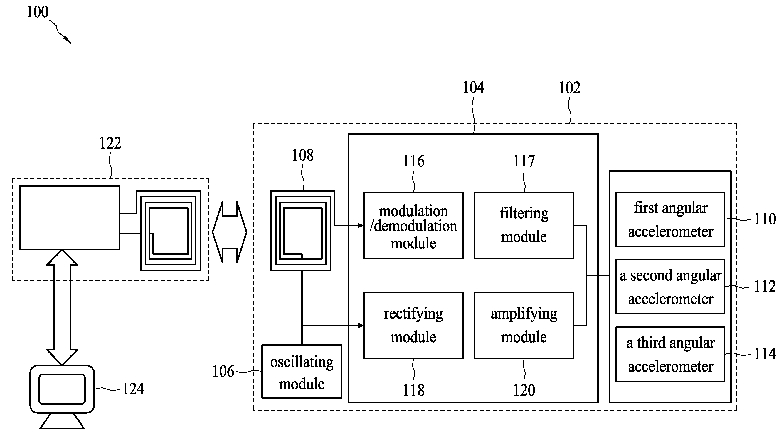
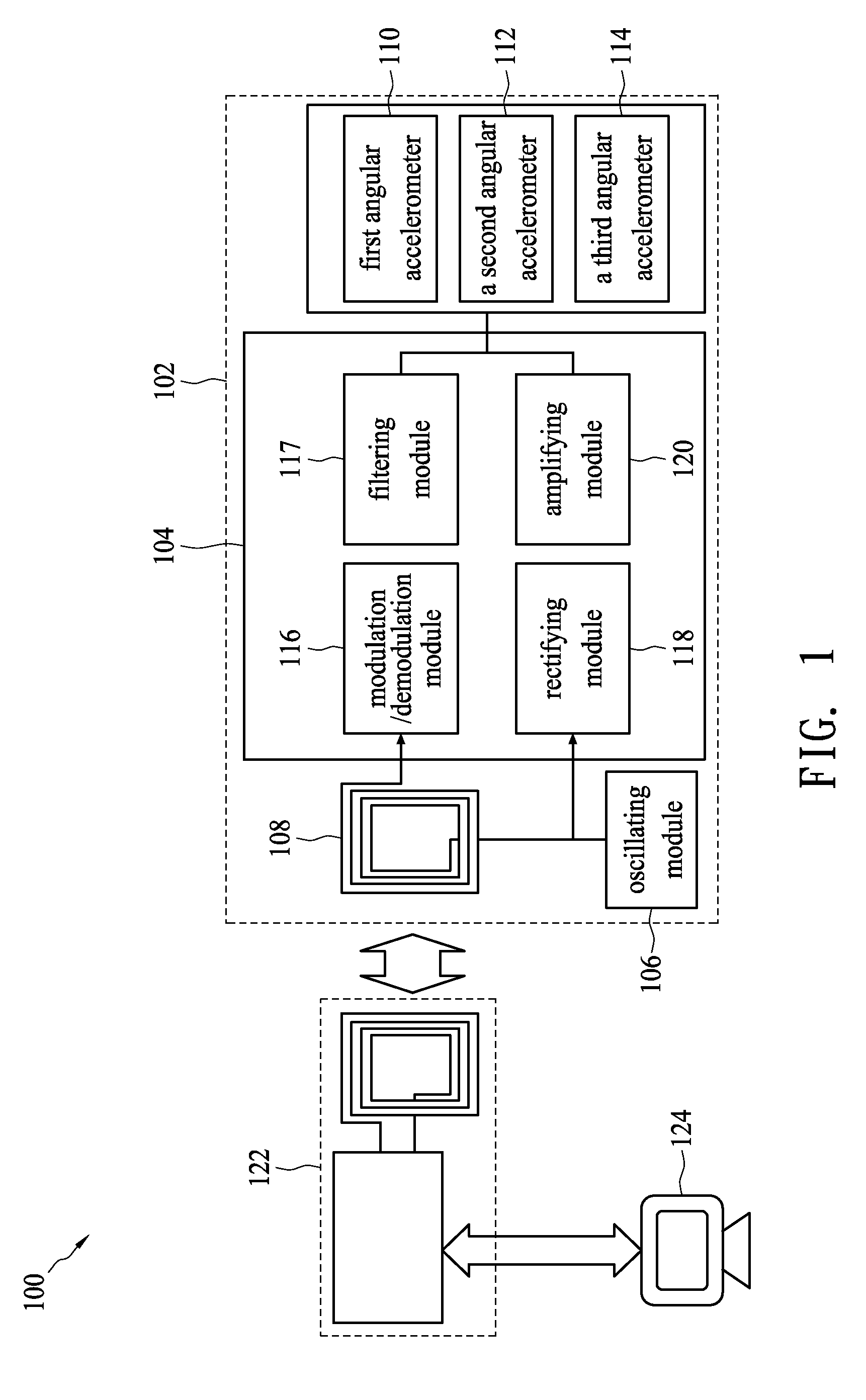
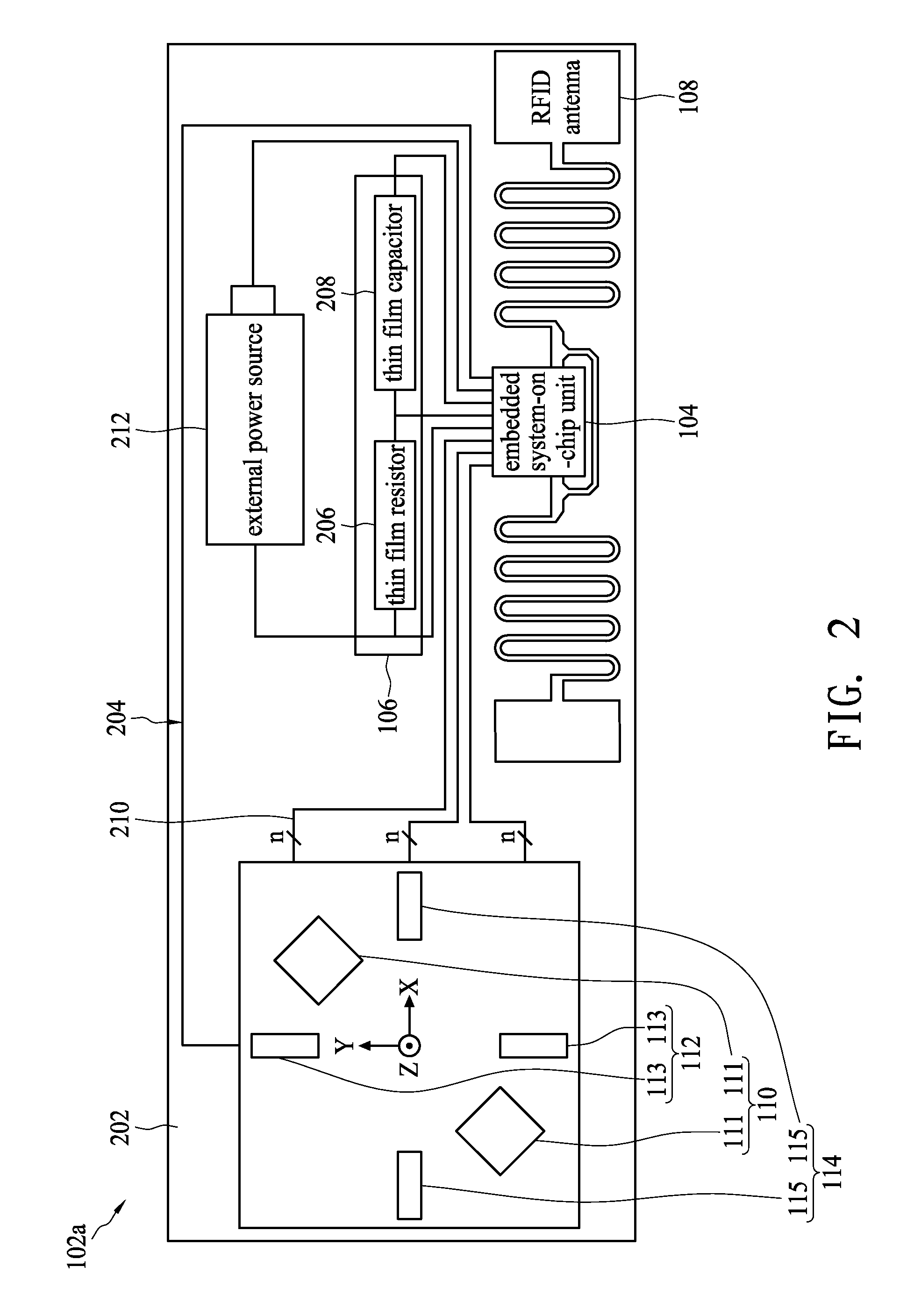
[0008]The present invention proposes an RFID, Bluetooth as well as zigbee based thermal bubble type angular accelerometer. The thermal bubble type angular accelerometer is manufactured on a flexible substrate so as to reduce the manufacturing cost. Furthermore, the thermal bubble type angular accelerometer and an RFID, Bluetooth as well as zigbee antenna are integrally formed on the same substrate, facilitating convenient use.

Problems solved by technology

However, these microstructures always deform when they are under the influence of force, resulting in fatigue and aging.
Therefore, the angular accelerometer with such microstructures has a short lifespan.
Because silicon dioxide has low thermal conductivity (1.5 W / (m−K)), heat transfer in the accelerometers is adversely affected so that the temperature of the lower portion of a gas chamber is low, resulting in poor sensitivity of the thermistors.
In addition, the poor heat transfer also affects the sensitivity of the thermistors in response to acceleration.
However, under high working temperature, the silicon dioxide support for supporting the heaters and the thermistors may expand and shrink when the accelerometer is turned on and off, resulting in material fatigue and aging, reducing the lifespan of the accelerometer.
However, air contains oxygen, which may oxidize the heaters, and if volatile liquid is used, the volatile liquids may chemically react with the components in accelerometers, lowering their measurement accuracy after the accelerometers have been operated for a while, and reducing the lifespan of the accelerometers.
In summary, traditional angular accelerometers have short lifespans due to their easily aged microstructures, and require high temperature processes during manufacture, along with other shortcomings such as high cost, high energy consumption, material oxidation, aging, and low performance.

Method used


Image

  • Thermal Bubble Type Angular Accelerometer
  • Thermal Bubble Type Angular Accelerometer
  • Thermal Bubble Type Angular Accelerometer

Examples


Embodiment Construction

[0031]The present invention discloses a thermal bubble type angular accelerometer. The thermal bubble type angular accelerometer is formed with the combination of the technique of manufacturing a thermal type angular accelerometer on a flexible substrate and the technique of radio frequency identification communication. Therefore, the thermal bubble type angular accelerometer of the present invention is convenient to use and can be manufactured at low cost.

[0032]One aspect of the present invention is that the support member of the thermal bubble type angular accelerometer of the present invention is manufactured of a material with high thermal conductivity such as aluminum nitride or silicon nitride. Particularly, aluminum nitride has thermal conductivity of 160 to 320 W / (m−K), close to that of copper, which has thermal conductivity of 400 W / (m−K). Comparatively, the support member of a traditional accelerometer is made of silicon dioxide having low thermal conductivity of 1.5 W / (m−...


PUM

PropertyMeasurementUnit
Timeaaaaaaaaaa
Flexibilityaaaaaaaaaa
Molecular weightaaaaaaaaaa

Abstract

An RFID, Bluetooth as well as zigbee based thermal bubble type angular accelerometer includes a flexible substrate, a base layer, at least one cavity, and at least one sensing assembly. The base layer is formed on the flexible substrate. The at least one cavity is formed on the base layer. The at least one sensing assembly is suspended over the at least one cavity. The sensing assembly comprises a heater and two temperature sensing elements, wherein the two temperature sensing elements are substantially symmetrically disposed on opposite sides of the heater, and the heaters and the two temperature sensing elements extend in a radial direction.

Description

BACKGROUND OF THE INVENTION[0001]1. Field of the Invention[0002]The present invention relates to a thermal bubble type angular accelerometer, and relates more particularly to a thermal bubble type angular accelerometer that uses radio frequency identification, Bluetooth as well as zigbee technologies on the flexible substrate for communication and can be manufactured using low temperature processes.[0003]2. Description of the Related Art[0004]Small angular accelerometers based on different measuring principles have been developed to meet the requirements of measuring angular acceleration. One small angular accelerometer has an ingenious structure, such as a comb structure or a vibratory structure, formed using a semiconductor wafer. By measuring the change of parasitic capacitance or resonant frequency during the rotation of the microstructures, the angular velocity or the inclined angle of the microstructures can be calculated. However, these microstructures always deform when they...

Claims


Application Information

Patent Timeline
IPC IPC(8): G01P15/00G01P15/02
CPCG01P15/008G01P15/0888G01P15/0802H01L2224/32145H01L2224/73265
Inventor LIN, JIUM MING
Owner CHUNG HUA UNIVERSITY
Learn More