
Organic Solar Cell with Oriented Distribution of Carriers and Manufacturing Method of the Same

Inactive Publication Date: 2011-05-05
NATIONAL TSING HUA UNIVERSITY
View PDF7 Cites 15 Cited by
  • Summary
  • Abstract
  • Description
  • Claims
  • Application Information

AI Technical Summary

Benefits of technology

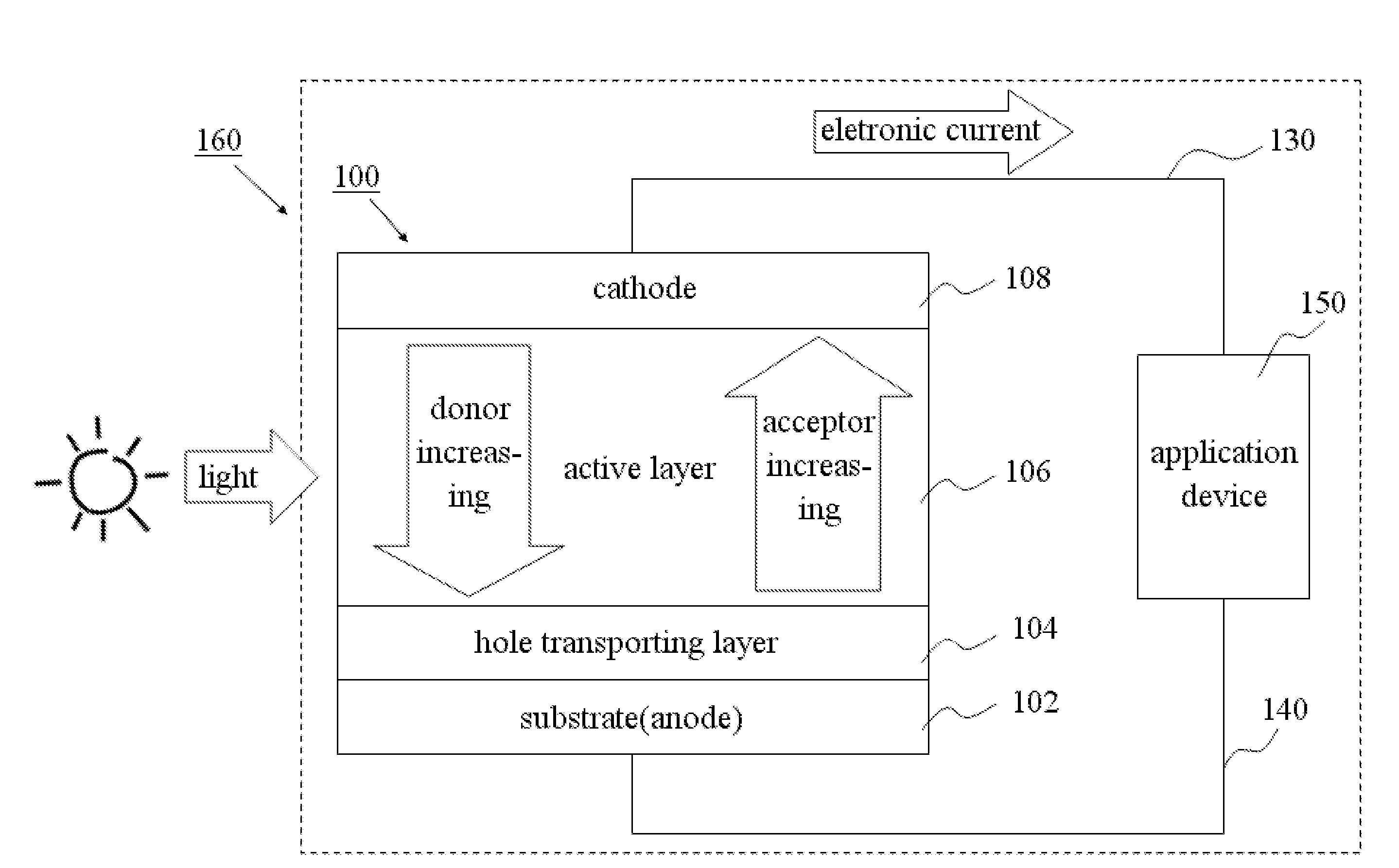
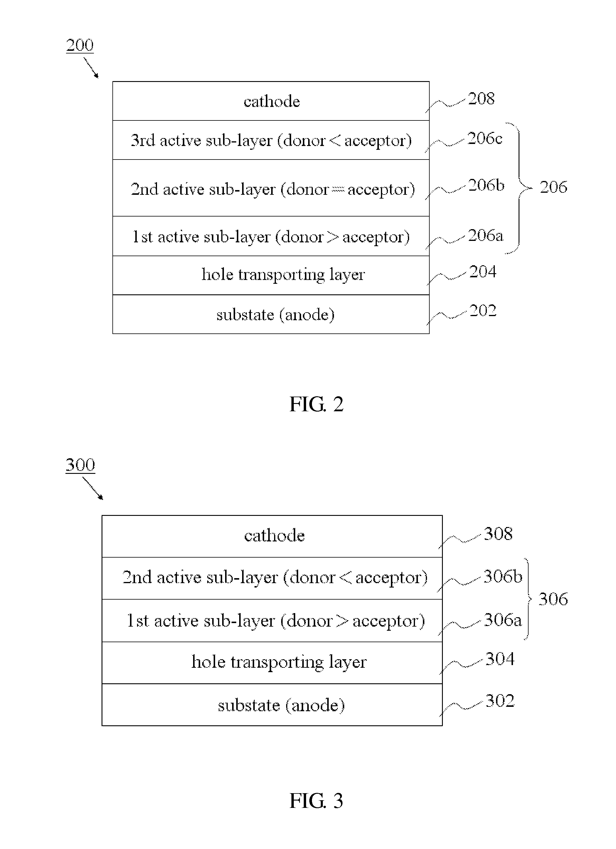
[0012]One of the advantages of the embodiments of the present invention is that the multilayer without interlayer miscibility phenomenon, more particular, the active sub-layers without interlayer miscibility phenomenon, can be formed utilizing the buffer layer method, to form an active layer with concentration variation of electron donors and electron acceptors, i.e., the active layer with oriented distribution of carriers, and the organic solar cell and organic solar system with oriented distribution of carriers are also provided.
[0013]Another aspect of the embodiments of the present invention is that the potential gradients of carriers can be formed upon the variations of the ratios of the electron donors to the electron acceptors between the different active sub-layers. Upon weak forward bias and light bias, the carrier extraction efficiency is obviously improved, and the efficiencies of the organic solar cell and / or the organic solar system are also improved. Further, the performances upon various parameters, such as parallel resistance, short current, fill factor and / or energy conversion efficiency are also improved.

Problems solved by technology

Thus, they become highly-concerned about and getting new development unceasingly.
However, there are some limiting factors which come from the natural properties of the polymer material, such as lower carrier (electron / electric hole) mobility, higher exciton binding energy, and the interlayer mixing phenomenon.
Therefore, the organic solar cell, especially the polymer organic solar cell, generally has the shortcomings of owning low light absorption efficiency and low carrier extraction efficiency, and they may be viewed as a bottleneck upon the development of the organic solar cell that is not yet be overcome.
However, in the specification of the disclosed buffer layer method, it is not provided about how to apply the buffer layer method on implementing the organic solar cell and how to overcome the shortcomings of the light absorption efficiency and carrier extraction efficiency therein.

Method used


Image

  • Organic Solar Cell with Oriented Distribution of Carriers and Manufacturing Method of the Same
  • Organic Solar Cell with Oriented Distribution of Carriers and Manufacturing Method of the Same
  • Organic Solar Cell with Oriented Distribution of Carriers and Manufacturing Method of the Same

Examples


Embodiment Construction

[0026]In the embodiments of the present invention, a multilayer coating process is applied to the active layer (light absorption layer), for manufacturing an organic solar cell with oriented-distribution of electron donors and electron acceptors. The probability of recombination of the carriers (including electrons and holes) before being transported to the corresponding electrodes (anode or cathode) is thus lowered.

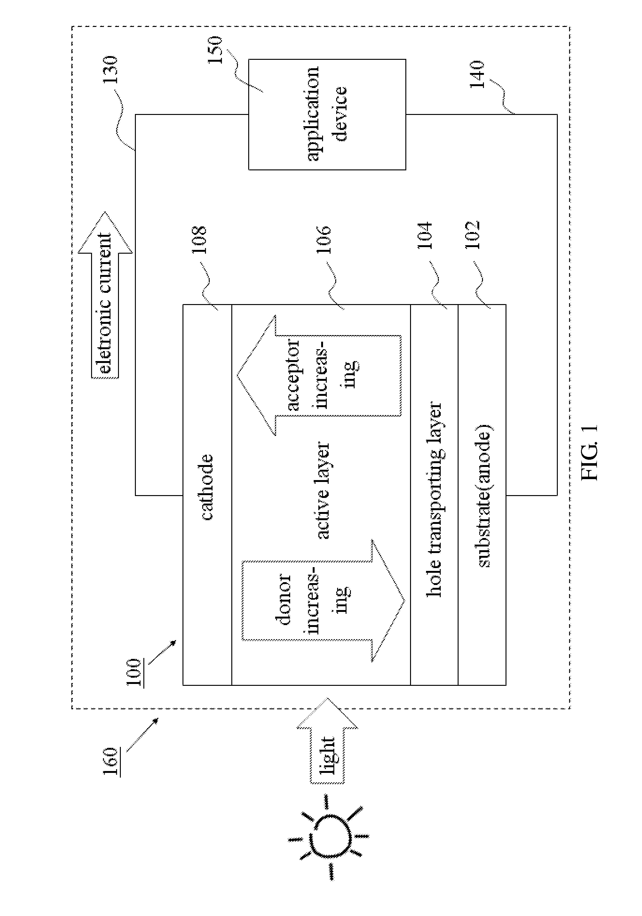
[0027]FIG. 1 shows the organic solar system with multilayer structure according to the embodiment of the present invention. The organic solar cell 100 comprises a substrate 102 formed on the bottom thereof, as an anode of the organic solar cell 100; a hole transporting layer (HTL) 104 formed on the substrate 102, for facilitating transportation of the electron holes; an active layer 106 formed on the HTL 104, for absorbing light energy (from the sun or other light sources), and therefore called a “light absorption layer”; and a cathode 108 formed on the active layer 106,...


PUM

PropertyMeasurementUnit
Electric potential / voltageaaaaaaaaaa
Efficiencyaaaaaaaaaa

Abstract

The present invention provides an organic solar cell with oriented distribution of carriers, which forming variation of distribution of electron donors and electron acceptors between active sub-layers of an active layer by utilizing buffer layer method, for improving carrier extraction efficiency and thus effectively enhancing performance of the organic solar. The present invention also provides a method for manufacturing an organic solar cell with oriented distribution of carriers.

Description

FIELD OF THE INVENTION[0001]The present invention is generally related to the field of the solar cell and, more particularly, to an organic solar cell including multi-layer structure, for forming oriented distribution of electron donors and electron acceptors.DESCRIPTION OF THE PRIOR ART[0002]Semiconducting conjugated polymers exhibit advantages such as cost effectiveness, feasibility to scale up, convenience for coating, moderate flexibility, etc. Therefore, in recent years, the industries have actively investigated during the development of the related technologies, which comprising organic light emitting diode (OLED), organic thin film transistor, organic solar cell, etc. When fabricating those on plastic substrates, further advantages such as flexibility and light-weightiness can be obtained for increasing the applicability. Furthermore, because of its flexibility, continuous roll-to-roll processing might be employed to lower the processing cost and increase the final throughput...

Claims


Application Information

Patent Timeline
IPC IPC(8): H01L51/46H01L51/48
CPCH01L51/0036H01L51/0037Y02E10/549H01L51/4253H01L2251/308H01L51/4246Y02P70/50H10K85/1135H10K85/113H10K30/211H10K30/30H10K2102/103H10K30/50
Inventor HORNG, SHENG-FUMENG, HSIN-FEILEE, MING-KUNWANG, JEN-CHUNKUO, TSUNG-HANG
Owner NATIONAL TSING HUA UNIVERSITY
Learn More