
Water distillation method and apparatusfor indirect evaporative coolers

a technology of indirect evaporation and water cooler, which is applied in vacuum distillation separation, separation processes, vessel construction, etc., can solve the problems of large amount of costly high-calorie heat energy required to conduct the process, high cost, and high cost, and achieves the effect of reducing the thermal energy required for evaporation and more efficient distillation processes

Inactive Publication Date: 2011-05-12
IDALEX TECH INC
View PDF24 Cites 17 Cited by
  • Summary
  • Abstract
  • Description
  • Claims
  • Application Information

AI Technical Summary

Benefits of technology

[0018]This invention provides more efficient processes of distillation. The thermal energy required for evaporation is decreased significantly by recycling the heat of condensation of the distillate.
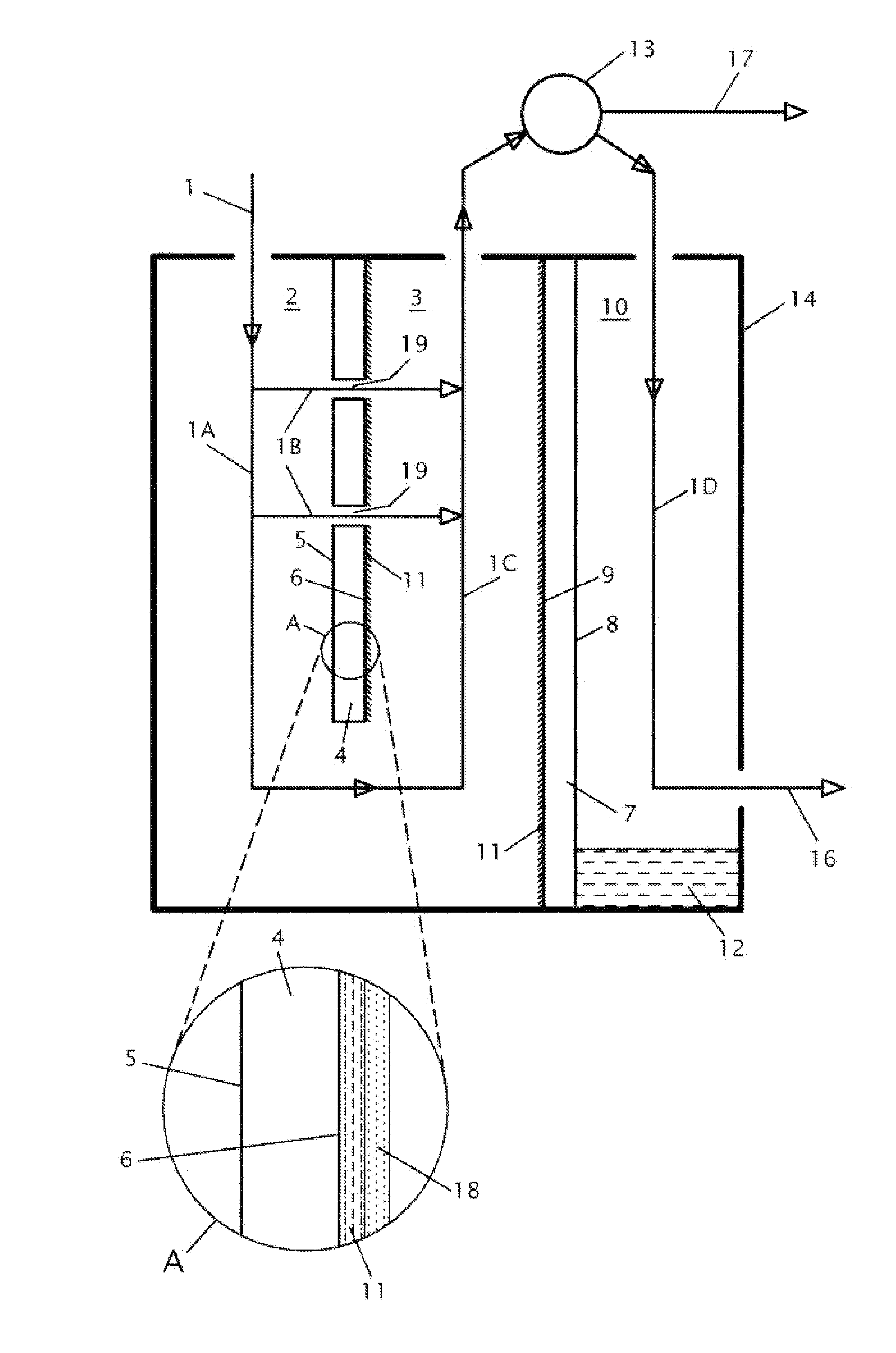
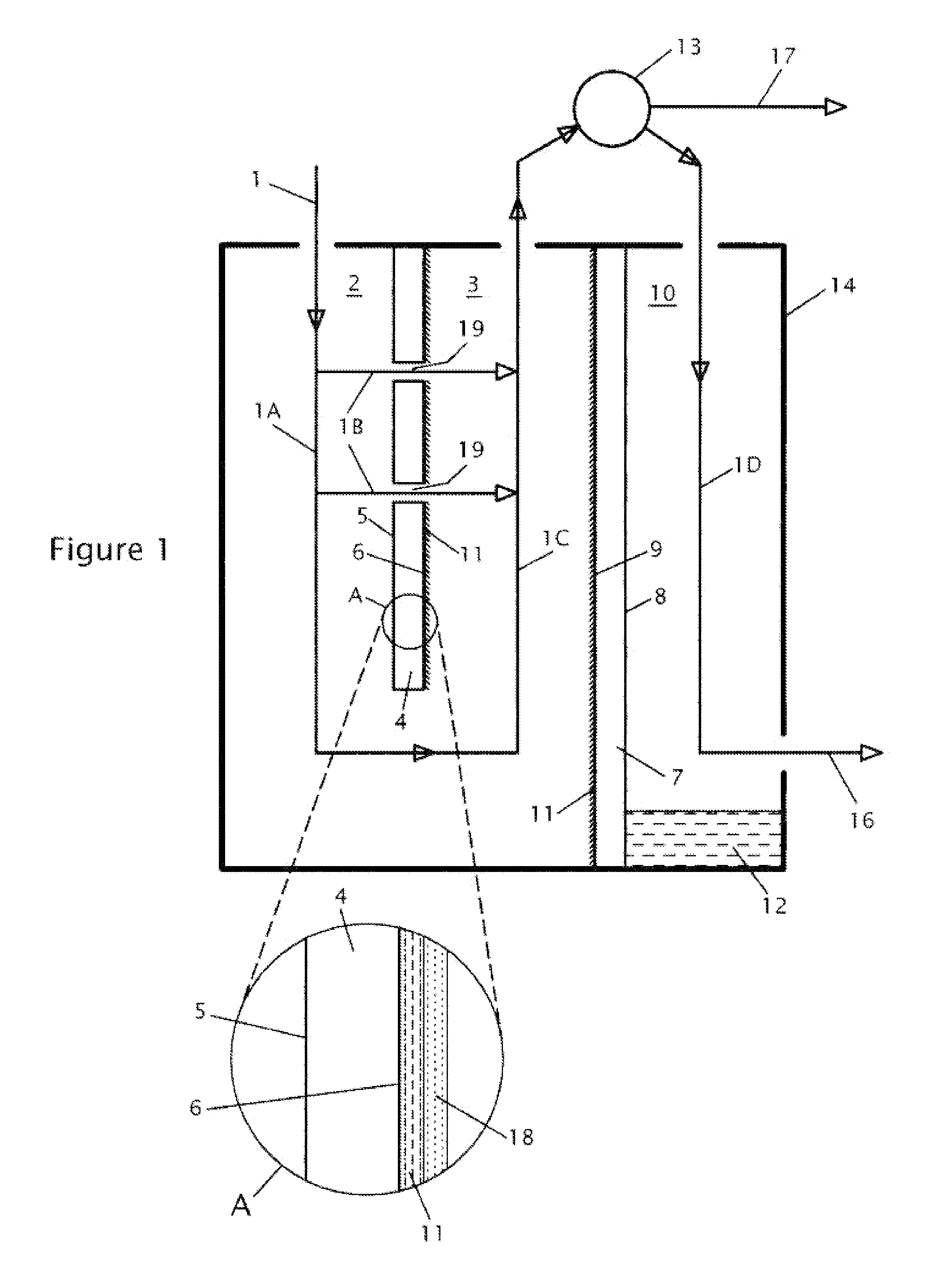
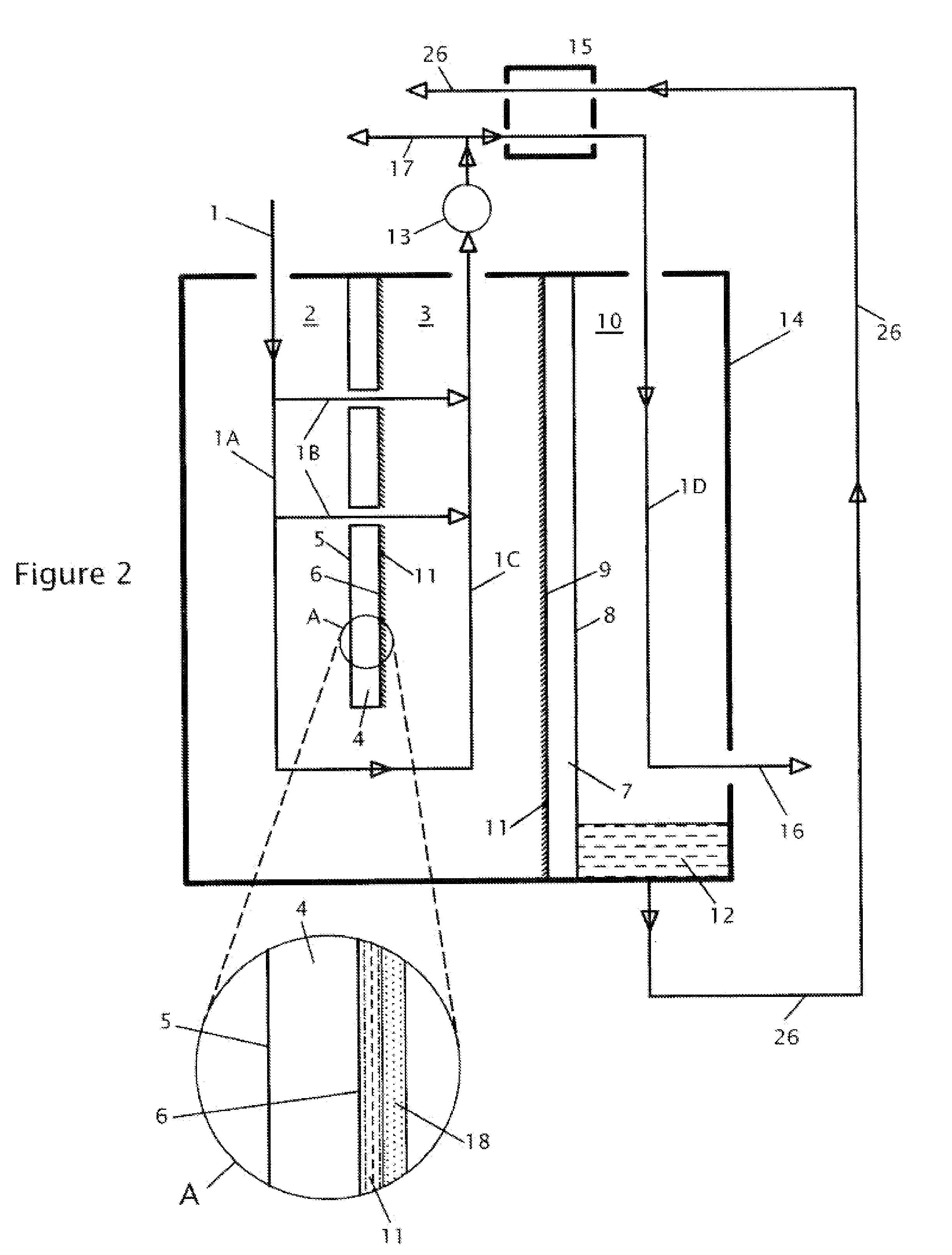
[0021]The input airflow is, for example, outside air. Airflow is first directed in to the cooling channel. In the cooling channel, the airflow is pre-cooled via contact with the dry side of the first plate, without changing its absolute humidity but reducing its temperature from ambient to substantially the dew point temperature of the input air. Part of the airflow is redirected through the plate, for example, via perforations, to the evaporative channel of the vessel, for direct contact with a solution covering a wick layer on the wet sides of the plates. In the evaporative channel, airflow becomes humidified with moisture evaporating from the solution. This process increases the temperature and the moisture content of the airflow.

Problems solved by technology

V. N. Slesarenko “Modern Techniques for Desalination of Sea and Saline Waters” published in 1973 by the Energia Publishers, Moscow, pp., 47-48).However, in this method, a large amount of costly high-calorie heat energy is required to conduct the process (around 600 kcal / kg under atmospheric pressure, which corresponds to approximately 695 watts per 1 kg of desalinated water).
These boiler-type distillers, however, require substantial amounts of electrical power to produce relatively little distilled water and are thus highly inefficient.
They are also extremely slow, often taking many hours to produce just a few gallons of distilled water.
Accordingly, this sort of distiller has not gained widespread acceptance or use.
Although this distiller provides some advantages because it uses solar energy instead electricity, its design is very complicated and efficiency of distillation is small.
The big disadvantage of these patents is significant expenses of the energy.
But in the past, the prior art types of evaporators have proved costly and troublesome when used continuously on a large scale.
Hot seawater is exceedingly corrosive.
Most prior art methods of obtaining fresh water from seawater have been most inefficient.
The yield of this process is very low.
But productivity of this atmospheric pressure desalination is small because processes of humidification and dehumidification are not efficient.
This system is still not as efficient as desired, and requires a divided vessel and condenser.
But all existing vacuum-process technologies of the water vapor compression cycle for producing distilled water have essential disadvantages.
First of all it is not efficient when the heat of condensation of water vapor is used as heat for evaporation.
Therefore pressures of condensation are high and this increases consumption of energy by the compressor and reduces the productivity of the water vapor compression cycle.
In addition, all or part of the heat of condensation is lost to the atmosphere without recovery.

Method used


Image

  • Water distillation method and apparatusfor indirect evaporative coolers
  • Water distillation method and apparatusfor indirect evaporative coolers
  • Water distillation method and apparatusfor indirect evaporative coolers

Examples


Embodiment Construction

[0038]Below is a table of reference numbers and elements used in the description below.

Reference Number Table 1airflow 2cooling channel 3evaporative channel 3′second evaporative channel 4first plate 5dry side of first plate 6wet side of first plate 7second plate 8dry side of second plate 9wet side of second plate10condensing channel11solution12distilled water13fan14water purifying vessel15water cooler16product airflow17working airflow18wick layer20, 21openings for product air22openings for working air23opening in second plate24baffle - cooling / condensing25baffle - evaporation26distilled water pipeline27solution pipeline28recovery channels29fan30dual plate31dryportions of dual plate32wetportions of dual plate33solid dessicant34output channel35vacuum channel36compressor37vacuum channel plate38vacuum / condenser plate39condense / evaporate plate40liquid desiccant41heat transfer plate43pump - weak desiccant44pump - concentrated desiccant45added heat47solution supply tank48solution supply pi...


PUM

PropertyMeasurementUnit
temperaturesaaaaaaaaaa
volume percentaaaaaaaaaa

Abstract

Apparatus for distilling a fluid such as water includes a vessel and heat transfer plates within the vessel structures to form at least one each cooling channel, evaporative channel, and condensing channel. Air enters the vessel and passes through the cooling channel, where it is cooled due to evaporation taking place in an adjacent evaporative channel. In the evaporative channel, input fluid is supplied to the walls of the heat transfer plates facing into the evaporative channel and evaporation forms vapor. The vapor is condensed in a condensing channel. In some embodiments, an evaporation channel forms a vacuum chamber and a condensing channel forms a compression chamber.

Description

FIELD OF THE INVENTION[0001]The present invention relates to water treatment, and more particularly to methods and apparatus for distillation or desalination of fluids such as water.BACKGROUND ART[0002]Distillation is a common method for generating potable water from otherwise unsafe water sources (such as seawater or polluted ground water). With distillation, water is heated to boiling, and the resultant vapor is collected and condensed, producing distilled water.[0003]Known in the art is a method of distillation or desalination of water wherein water is evaporated from an aqueous salt solution when the solution comes into contact with air and distilled water is subsequently retrieved from the thus moistened air by condensation (cf. V. N. Slesarenko “Modern Techniques for Desalination of Sea and Saline Waters” published in 1973 by the Energia Publishers, Moscow, pp., 47-48).However, in this method, a large amount of costly high-calorie heat energy is required to conduct the process...

Claims


Application Information

Patent Timeline
Patent Type & Authority Applications(United States)
IPC IPC(8): B01D3/00B01D3/10B01D5/00
CPCB01D1/22B01D3/346B01D1/2893Y02A20/124
Inventor MAISOTSENKO, VALERIYGILLAN, LELAND E.GILLAN, ALAN D.GILLAN, RICK J.
Owner IDALEX TECH INC
Learn More