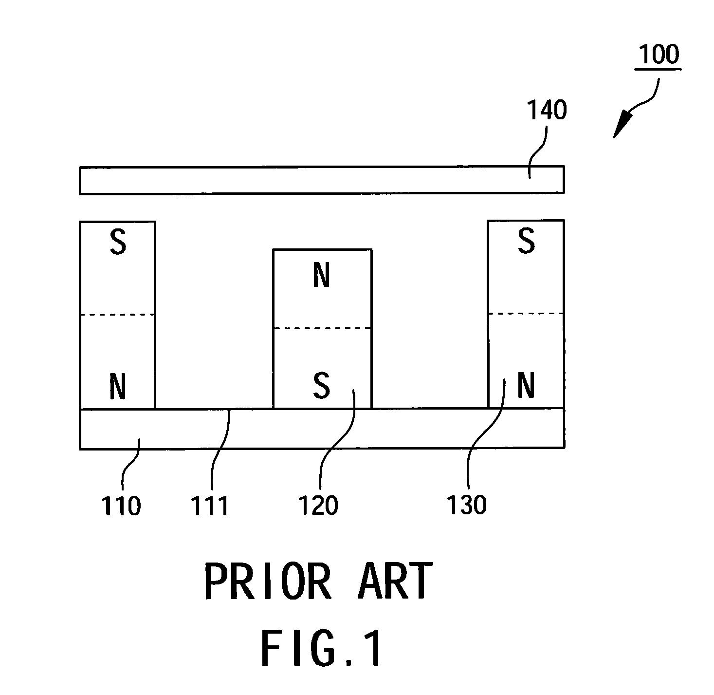
Magnetron sputter

a sputter and magneton technology, applied in the field of magneton sputter, can solve the problems of low gas ionization rate, low sputtering efficiency, and target cannot be used anymore, so as to improve sputtering efficiency, reduce cost, and improve the effect of target use li

Inactive Publication Date: 2011-05-12
NAT SUN YAT SEN UNIV
View PDF6 Cites 3 Cited by
  • Summary
  • Abstract
  • Description
  • Claims
  • Application Information

AI Technical Summary

Benefits of technology

[0007]A primary object of the present invention is to provide a magnetron sputter which comprises a carrier, a magnet assembly, at least a middle magnetic ring, a target and at least a conducting magnetic ring. The carrier has a carrying surface, and the magnet assembly is disposed on the carrying surface of the carrier having a permanent magnet and an external magnetic ring disposed around the permanent magnet. The middle magnetic ring is disposed between the permanent magnet and the external magnetic ring. The target is disposed above the magnet assembly having a first surface facing the carrying surface and a second surface opposite to the first surface. The conducting magnetic ring is disposed on the first surface of the target. Extra elements such as the middle magnetic ring, the conducting magnetic ring and the external coil are added to the magnetron sputter without changing original structure for adjusting intensity and direction of magnetic field so as to improve sputtering efficiency and use lifetime of the target, thereby lowering cost and increasing economic efficiency.

Problems solved by technology

In most dc sputtering application, the positively charged particles are in rectilinear motion along electric field direction so gas ionization rate is low, because most the gas atoms are uncharged unable to be accelerated for sputtering resulting in low sputtering efficiency.
The known magnetron sputter structure could cause problems on the target surface, such as non-uniform ion distribution and annular etching shape, and if the etching area is too big, the target cannot be used any more.
When the magnetron sputter 100 is activated, since magnetic line of force within magnetic field travels along fixed direction, partially special area of the target 140 could be overused, etched and even penetrated, which results in lowering usage rate of the target 140 as well as electrons and ions within the magnetron sputter 100 are affected by electromagnetic field so coating efficiency and uniformity of substrate will become worse as to cause problem of low sputtering efficiency.

Method used


Image

  • Magnetron sputter
  • Magnetron sputter
  • Magnetron sputter

Examples


Embodiment Construction

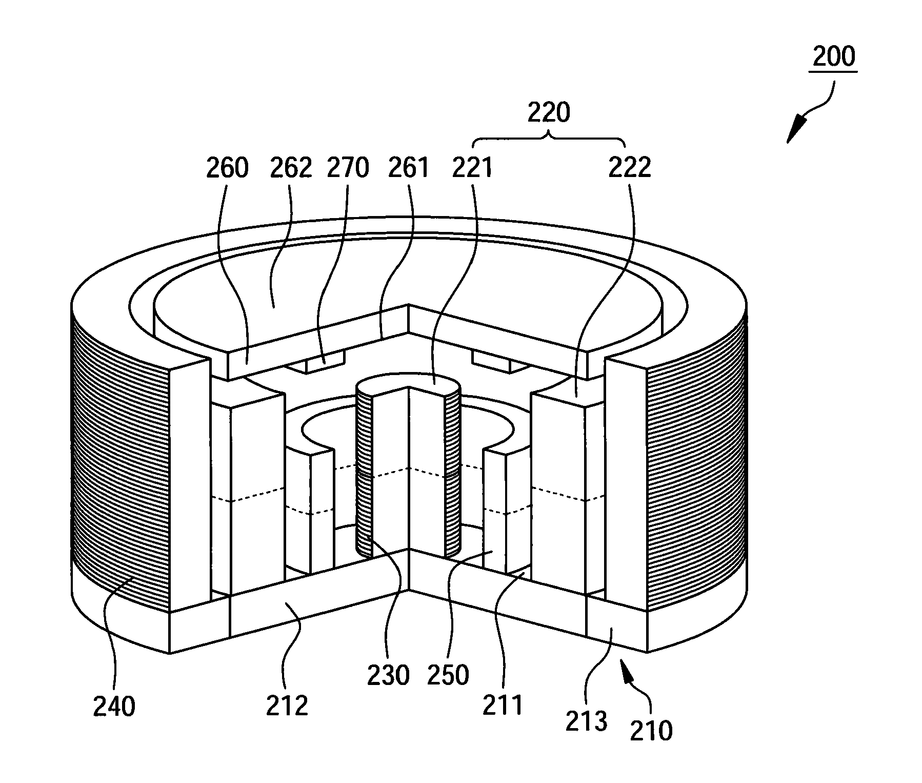
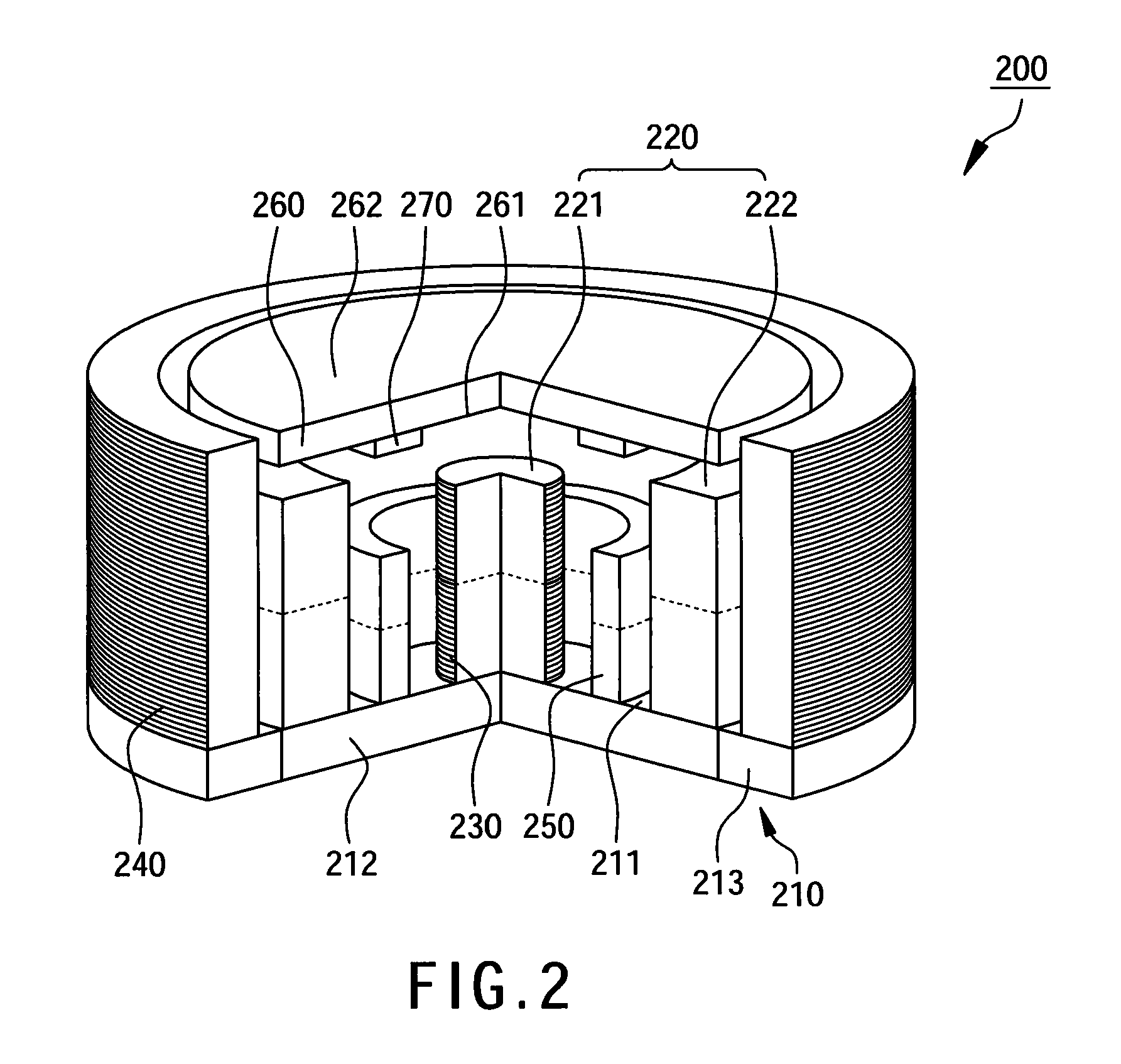
[0012]With reference to FIGS. 2 and 3, a magnetron sputter 200 in accordance with a preferred embodiment of the present invention comprises a carrier 210, a magnet assembly 220, an internal coil 230, an external coil 240, at least a middle magnetic ring 250, a target 260 and at least a conducting magnetic ring 270. The carrier 210 has a carrying surface 211, the magnet assembly 220 is disposed on the carrying surface 211 of the carrier 210 comprising a permanent magnet 221 and an external magnetic ring 222 disposed around the permanent magnet 221. Within this embodiment, the permanent magnet 221 has a shape of pillar, a preferred diameter about 12 mm and a preferred radial thickness about 20 mm. The external magnetic ring 222 also has a preferred internal diameter about 38 mm, a preferred external diameter about 50 mm and a preferred radial thickness about 22 mm. The permanent magnet 221 has a first magnet N pole and a first magnet S pole, and the external magnetic ring 222 has a se...


PUM

PropertyMeasurementUnit
diameteraaaaaaaaaa
diameteraaaaaaaaaa
diameteraaaaaaaaaa

Abstract

A magnetron sputter comprises a carrier, a magnet assembly, at least a middle magnetic ring, a target and at least a conducting magnetic ring. The magnet assembly is disposed on a carrying surface of the carrier comprising a permanent magnet and an external magnetic ring. The middle magnetic ring is disposed between the permanent magnet and the external magnetic ring of the magnet assembly. The target is disposed above the magnet assembly having a first surface which faces the carrying surface. The conducting magnetic ring is disposed on the first surface.

Description

FIELD OF THE INVENTION[0001]The present invention is generally relating to a magnetron sputter, more particularly to a magnetron sputter which can enhance sputtering efficiency and improve use lifetime of target.BACKGROUND OF THE INVENTION[0002]Semiconductor industry is generally employed in various fields, such as information, communication, consumer electronics, industrial instruments and transportation. For example, ultra purity aluminum-titanium sputtering used in semiconductor fabricating industry, silver-aluminum alloy and complex alloy phase change sputtering used in compact disk fabricating industry, indium tin oxide (ITO) among transparent conductive oxide (TCO) film and aluminum alloy circuit layer sputtering used in TFT-LCD fabricating process, etc. The magnetron sputtering method mentioned within the foregoing fabricating processes is employed for coating which is to form a thin film on substrates to allow the substrate surface having characters of good-looking, anti-fri...

Claims


Application Information

Patent Timeline
Patent Type & Authority Applications(United States)
IPC IPC(8): C23C14/35
CPCC23C14/3407H01J37/3458H01J37/3452C23C14/35
Inventor LIU, CHENG-TSUNGLAI, MING-CHIH
Owner NAT SUN YAT SEN UNIV
Why Eureka
Try Eureka