Photoelectric conversion element

a conversion element and photoelectric technology, applied in the field of photoelectric conversion elements, can solve the problem that the photoelectric conversion efficiency is not necessarily achieved, and achieve the effect of high photoelectric conversion efficiency

Inactive Publication Date: 2011-05-19
SUMITOMO CHEM CO LTD
View PDF3 Cites 10 Cited by
  • Summary
  • Abstract
  • Description
  • Claims
  • Application Information

AI Technical Summary

Benefits of technology

[0006]It is an object of the present invention to provide a photoelectric conversion element which is free from leakage of a liquid material and also has high photoelectric conversion efficiency.

Problems solved by technology

However, in a dye-sensitized solar battery using a charge transport layer containing poly(3-hexylthiophene), sufficient photoelectric conversion efficiency is not necessarily achieved and it is desired to further improve the photoelectric conversion efficiency.

Method used


Image

  • Photoelectric conversion element
  • Photoelectric conversion element
  • Photoelectric conversion element

Examples


example 1

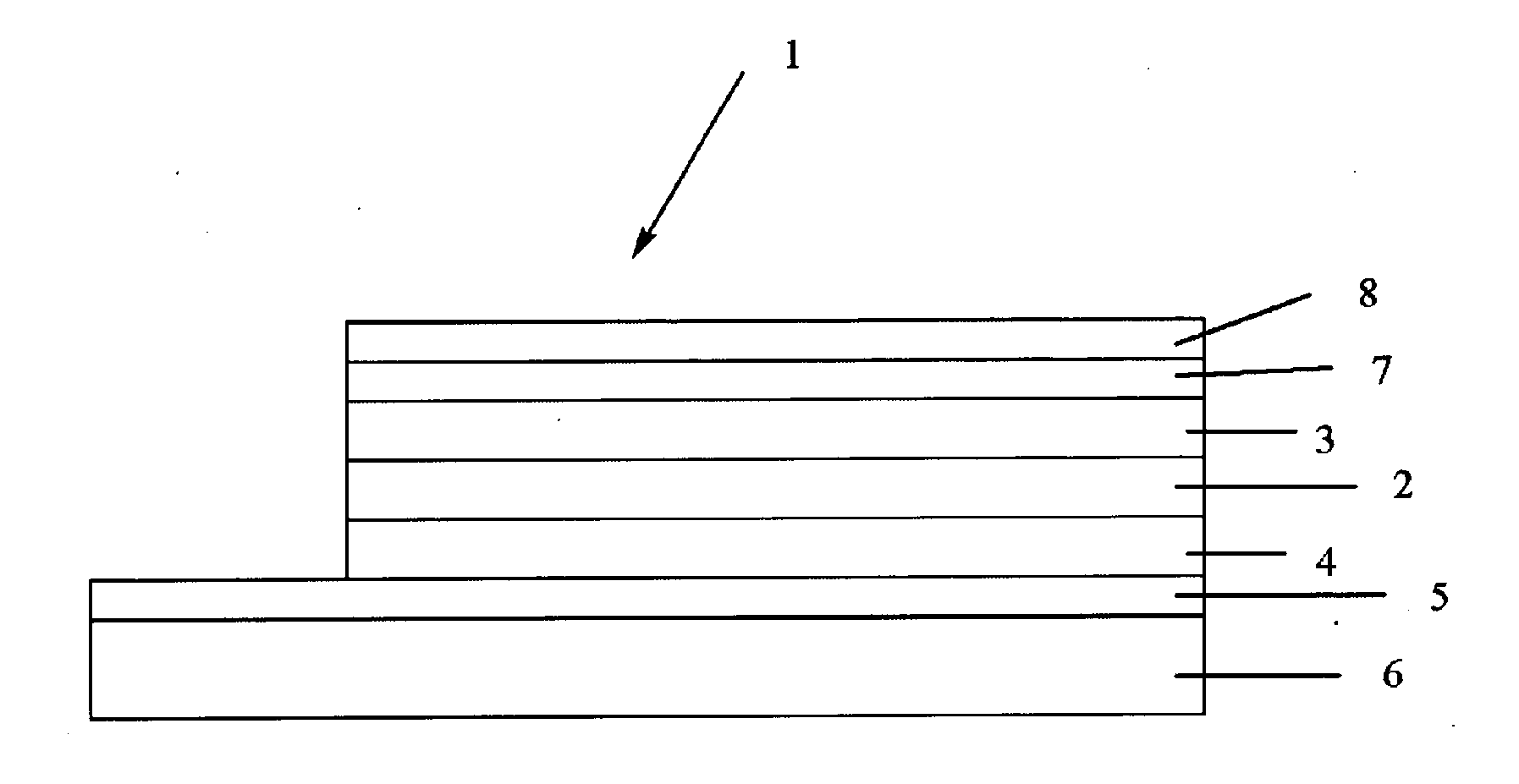
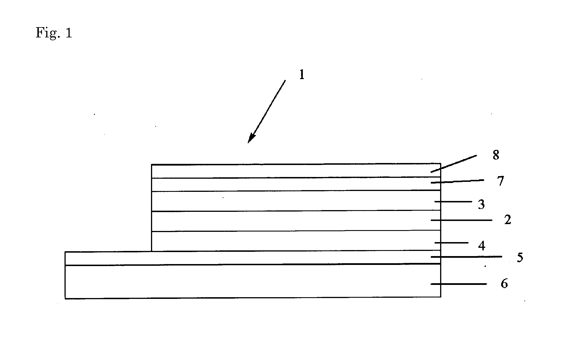
[0273]On a transparent conductive glass substrate 6 on which a F (fluorine)-doped SnO2 thin film (first electrode 5) is formed, a dense layer 4 was formed by coating titania sol PASOL HPW-10R manufactured by Catalysts&Chemicals Industries Co., Ltd. using a spin coating method and firing at 450° C. for 30 minutes. After firing, a titania paste (Solaronix Titananoxide D) manufactured by Solaronix was further coated by a spin coating method and then fired at 450° C. for 30 minutes to form a porous semiconductor material. Next, the porous semiconductor material described above was immersed in a solution prepared by mixing a mixed solvent of acetonitrile and tertiary butyl alcohol in a ratio of 1:1 (volume ratio) with a ruthenium dye (product name: Ruthenium 520-DN, HOMO level: −5.25 to −5.45 eV) manufactured by Solaronox. Whereby, a photoelectrode 2 made of a sensitizing dye-adsorbed mesoporous titanium dioxide having a film thickness of about 2 μm to 4 μm was formed. Then, 2% by weight...


PUM

PropertyMeasurementUnit
number average molecular weightaaaaaaaaaa
hole mobilityaaaaaaaaaa
electrically conductiveaaaaaaaaaa

Abstract

A photoelectric conversion element comprising a first electrode, a second electrode, a functional layer arranged between the first electrode and the second electrode, and a porous semiconductor material arranged between the first electrode and the functional layer. The functional layer contains a polymer compound having an aromatic amine residue, and a dye is adsorbed on the porous semiconductor material. The photoelectric conversion element may additionally have a dense layer between the first electrode and the functional layer, and a dye may be absorbed on a part of the functional-layer-side surface of the dense layer. The photoelectric conversion element may additionally have an organic layer between the functional layer and the second electrode.

Description

TECHNICAL FIELD[0001]The present invention relates to a photoelectric conversion element.BACKGROUND ART[0002]A dye-sensitized solar battery has been developed as one of photoelectric conversion elements. The dye-sensitized solar battery comprises first and second electrodes for taking out an electric power, a semiconductor material containing a dye adsorbed thereon, and a charge transport layer provided to cover the semiconductor material. In a dye-sensitized solar battery in which an iodine solution is used in a charge transport layer, one with a photoelectric conversion efficiency of more than 10% has been reported.[0003]When an iodine solution is used in a charge transport layer, the electrode or the like may be corroded by iodine contained in the charge transport layer and deterioration of photoelectric conversion characteristics may be caused by volatilization of the iodine solution. Furthermore, since the charge transport layer is liquid, damage may cause leakage of a liquid c...

Claims


Application Information

Patent Timeline
Patent Type & Authority Applications(United States)
IPC IPC(8): H01L51/46
CPCC07C211/54C07D471/04H01G9/2031H01G9/2059H01L51/0059Y02E10/549H01L51/42H01L51/4226H01L2251/306Y02E10/542H01L51/0072H10K85/631H10K85/6572H10K30/151H10K30/00H10K2102/102
Inventor KATO, TAKEHITO
Owner SUMITOMO CHEM CO LTD
Why Eureka
Try Eureka