Microwave coagulation applicator and system with fluid injection

a technology of microwave coagulation and fluid injection, which is applied in the field of microwave coagulation applicators and systems with fluid injection, can solve the problems of limiting the creation of heated tails, and achieve the effects of reducing the length of energy absorption patterns, and being convenient to us

Active Publication Date: 2011-05-19
VARIAN MEDICAL SYSTEMS
View PDF98 Cites 37 Cited by
  • Summary
  • Abstract
  • Description
  • Claims
  • Application Information

AI Technical Summary

Benefits of technology

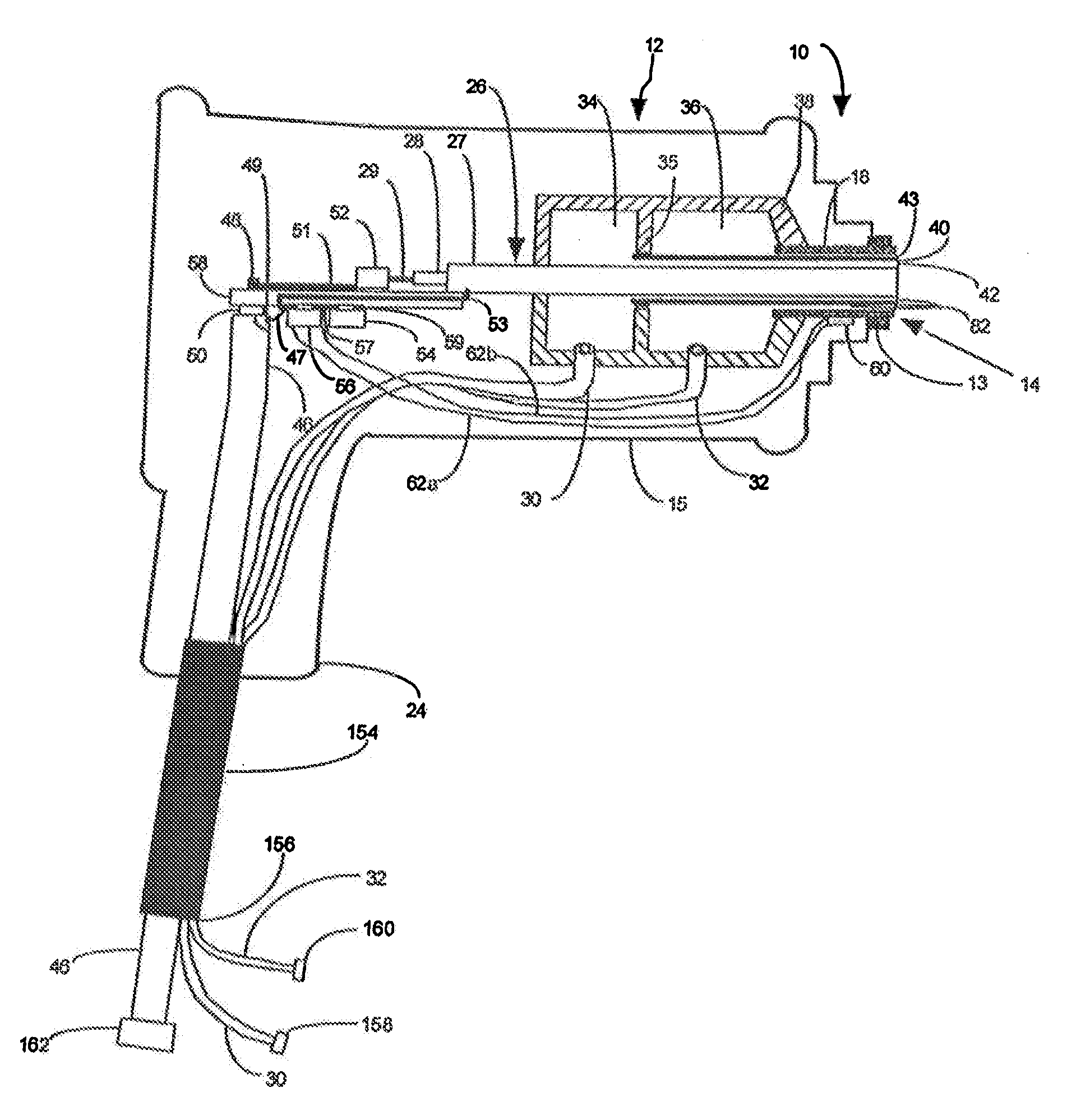
[0015]An embodiment of microwave applicator according to the invention for use in microwave coagulation and ablation treatments includes an elongate applicator body having an insertion (distal) end for insertion into a tissue region of a living body and an attachment (proximal) end for attachment to a source of microwave energy. An antenna for radiating microwave energy into tissue to be treated to produce a desired heating and ablation zone in the tissue is disposed toward the insertion end of the elongate applicator body. A coaxial microwave energy transmission line is disposed within the applicator body to conduct microwave energy from the attachment end of the applicator to the antenna. In order to limit the extent to which the microwave energy extends along the applicator from approximately the proximal end of the desired heating and ablation zone toward the proximal end of the applicator, thereby limiting the usual tail of the heating and ablation zone along the applicator toward the proximal end of the applicator, fluid can be injected along the applicator from approximately the proximal end of the desired heating zone a distance along the applicator body toward the proximal end of the applicator. By injecting fluid in this tissue region, tissue moisture and a higher dielectric constant is maintained in the tissue to maintain a higher microwave loss factor so that the microwave energy radiated into this tissue region is more rapidly attenuated as it travels along the outside of the inserted applicator. This feature aids in providing a more spherical coagulation pattern by reducing the energy that extends along the applicator extending through the tissue region that is not intended to be heated.
[0034]The design of a narrow separation gap between the conductive applicator insertion tip and the insertion end of the conductive outer sleeve provides a zone of high microwave intensity at the gap which can be used to coagulate tissues along the insertion track if the microwave power is applied as the microwave antenna is withdrawn from the treated tissue. This provides coagulation of tissue and blood vessels that may be along the insertion track as well as any disease tissue that may be along the track as the applicator is removed from the tissue. By providing regularly spaced depth markings on the elongate applicator and withdrawing the applicator from the living body in coordination with regular cadence sounds, a substantially constant rate of removal of the applicator from a living body can be achieved for effective track ablation. In addition to the regularly spaced depth markings, it has been found advantageous to also provide a warning marking visible on the outside of the elongate applicator body at a position a known distance toward the attachment end of the applicator from the portion of the applicator that creates the tissue ablation (heating zone or zone of ablation). As the applicator is withdrawn from the treated tissue, appearance of this warning marking indicates when the zone of track ablation or coagulation is getting close to the outer skin surface so that withdrawal of the applicator can be stopped at a desired position short of the skin area to avoid damaging or coagulating tissue in the skin area. Further, the fluid injection system can be controlled to stop fluid injection during this track ablation.

Problems solved by technology

Because cooling is not normally needed in the tissue to be heated during coagulation and ablation treatments, cooling is not provided in the area of the radiating antenna of the applicator where the heating of tissue is desired.
This provision of fluid to the tissue thereby limits the energy that extends along the applicator proximally from the desired heating and ablation zone into the area not intended to be heated, so limits the creation of the heated tail and results in a more spherical heating and ablation pattern.

Method used


Image

  • Microwave coagulation applicator and system with fluid injection
  • Microwave coagulation applicator and system with fluid injection
  • Microwave coagulation applicator and system with fluid injection

Examples


Embodiment Construction

[0055]Reference will now be made to the exemplary embodiments illustrated in the drawings, and specific language will be used herein to describe the same. It will nevertheless be understood that no limitation of the scope of the invention is thereby intended. Alterations and further modifications of the inventive features illustrated herein, and additional applications of the principles of the inventions as illustrated herein, which would occur to one skilled in the relevant art and having possession of this disclosure, are to be considered within the scope of the invention.

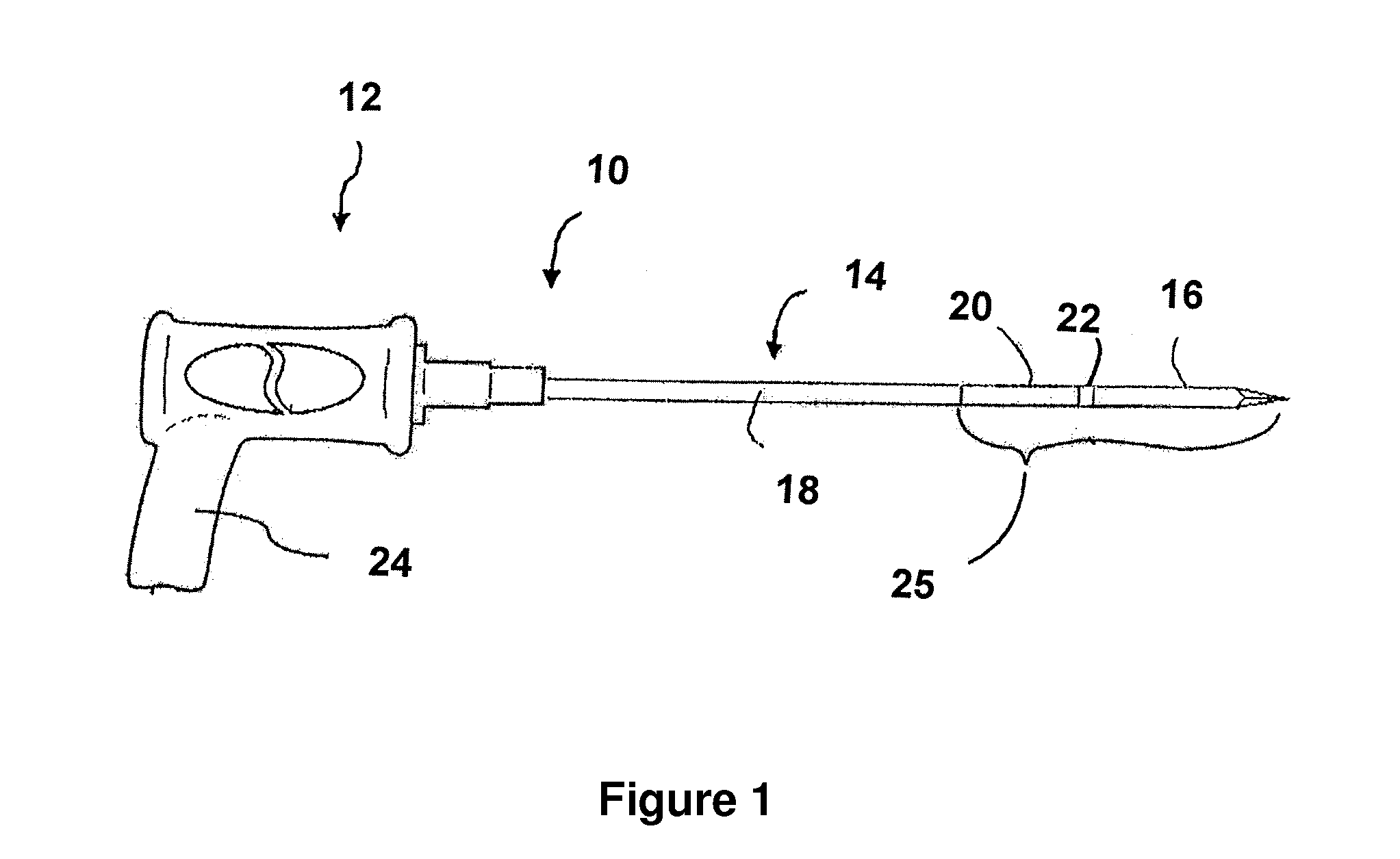
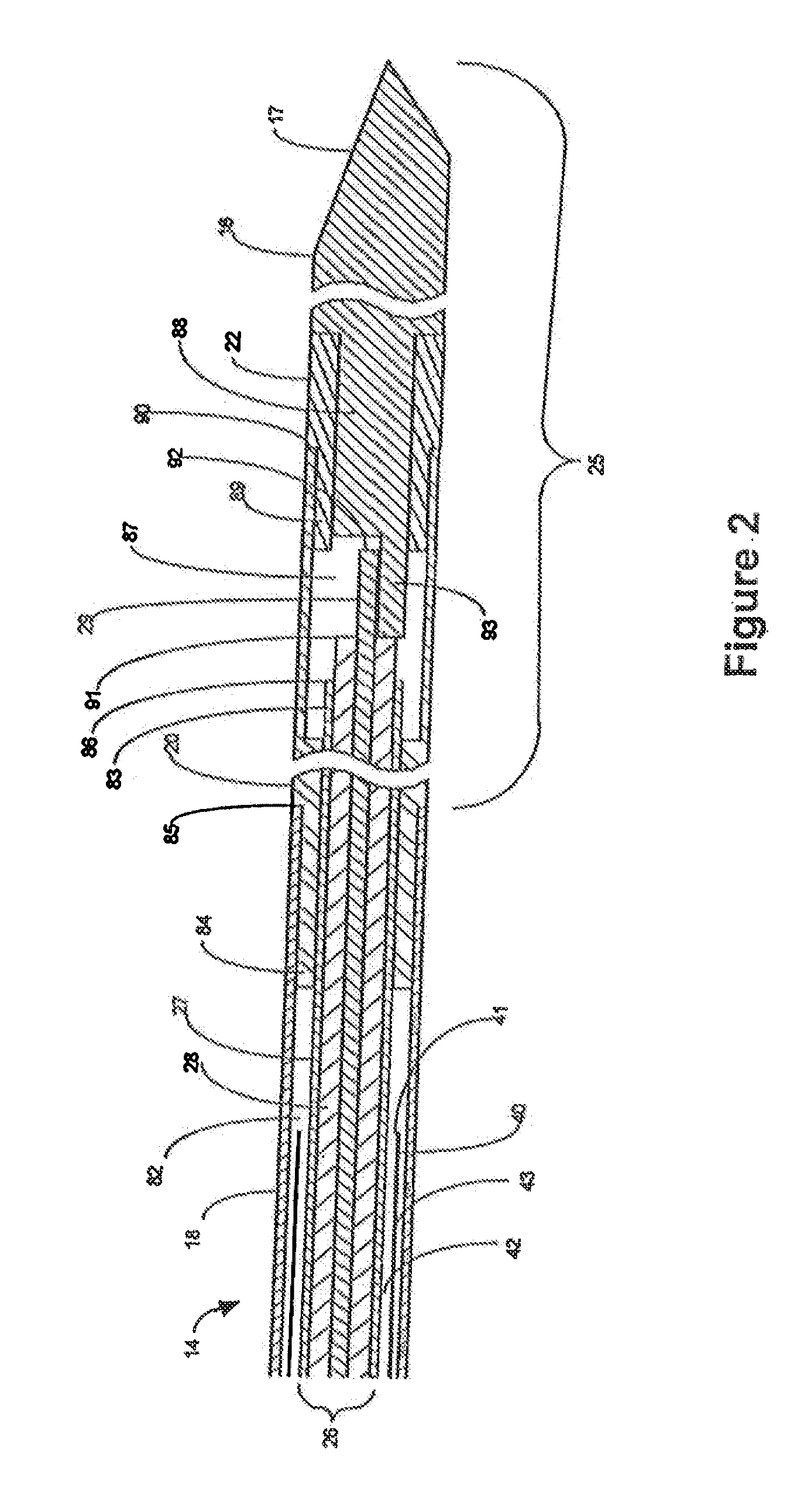
[0056]One embodiment of a microwave applicator of the invention for microwave coagulation and ablation treatment of diseased tissue within living body tissue is illustrated in FIG. 1. The applicator, referred to generally as 10, includes a handle 12 from which a substantially rigid elongate applicator body 14 extends with an insertion tip 16 forming the insertion end portion of the applicator for insertion into a...


PUM


Abstract

A microwave applicator for insertion into living body tissue for use in microwave coagulation and ablation treatments includes a microwave transmission line extending between an attachment end of the applicator and an antenna toward an insertion end of the applicator with an outer conductive sleeve forming an enclosed fluid space around the transmission line. A fluid circulation system circulates fluid in the fluid space. A portion of or all of the circulating fluid can be injected into tissue that surrounds the applicator body from approximately the proximal end of a desired heating zone produced by microwave energy radiated from the antenna along the applicator body toward the proximal end of the applicator to hydrate and wet the tissue outside the proximal end of the desired heating zone to reduce the drying of this tissue and limit extension of the heating and ablation zone proximally along the applicator body.

Description

RELATED APPLICATIONS[0001]This is a continuation-in-part of co-pending application Ser. No. 12 / 620,002, filed Nov. 17, 2009, and of co-pending application Ser. No. 12 / 689,195, filed Jan. 18, 2010, both entitled Microwave Coagulation Applicator and System, and both hereby incorporated herein by reference.BACKGROUND OF THE INVENTION[0002]1. Field[0003]This invention relates to electromagnetic radiation (EMR) therapy and more particularly to applicators and systems for applying electromagnetic energy to a treatment site in a living body to heat tissue needing treatment at the treatment site. The invention is useful particularly for treatments in the nature of microwave coagulation or ablation. A limitation found in current microwave antennas that are used for microwave coagulation and ablation is that the energy distribution pattern generally extends back along the applicator from the proximal end of the desired coagulation and ablation zone around the microwave energy radiating portio...

Claims


Application Information

Patent Timeline
Patent Type & Authority Applications(United States)
IPC IPC(8): A61B18/18
CPCA61B18/1815A61B2018/00023A61B2018/1892A61B2018/1869A61B2018/00029A61B2018/00577A61B2018/00589A61B2018/00815
Inventor TURNER, PAUL F.YOUD, THOMAS L.
Owner VARIAN MEDICAL SYSTEMS
Why Eureka
Try Eureka