Power supply apparatus

a technology of power supply apparatus and power supply line, which is applied in the direction of vacuum evaporation coating, plasma technique, coating, etc., can solve the problems of poor quality products, poor film forming, and inability to prevent the build-up of electrical charge-up, and achieve good thin film and suppress the occurrence of anomalous electric discharge

Inactive Publication Date: 2011-05-26
ULVAC INC
View PDF5 Cites 10 Cited by
  • Summary
  • Abstract
  • Description
  • Claims
  • Application Information

AI Technical Summary

Benefits of technology

[0008]In view of the above points, this invention has a problem of providing a power supply apparatus which is capable of suppressing the occu...

Problems solved by technology

As a result, when the electrical charge-up gets built up on the substrate to be processed (or on the insulating film formed on the surface of the substrate to be processed), the above-mentioned known AC power source was not able to prevent the electrical charge-up from getting bui...

Method used


Image

  • Power supply apparatus
  • Power supply apparatus
  • Power supply apparatus

Examples


Embodiment Construction

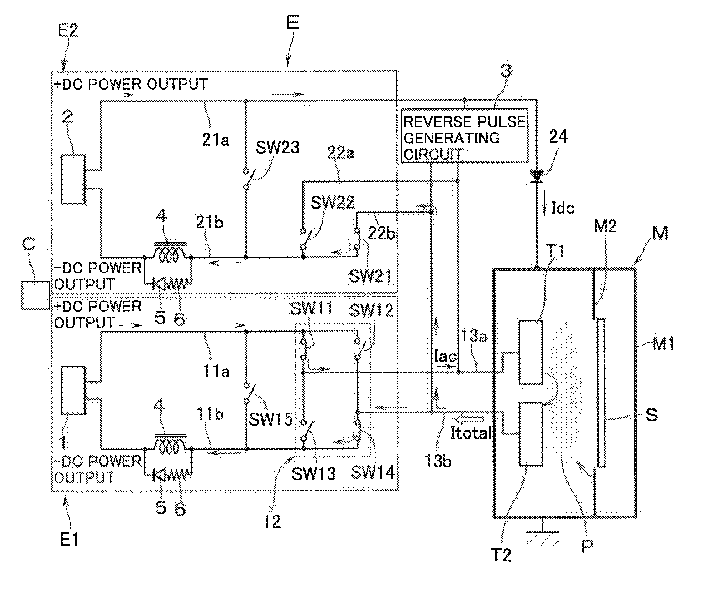
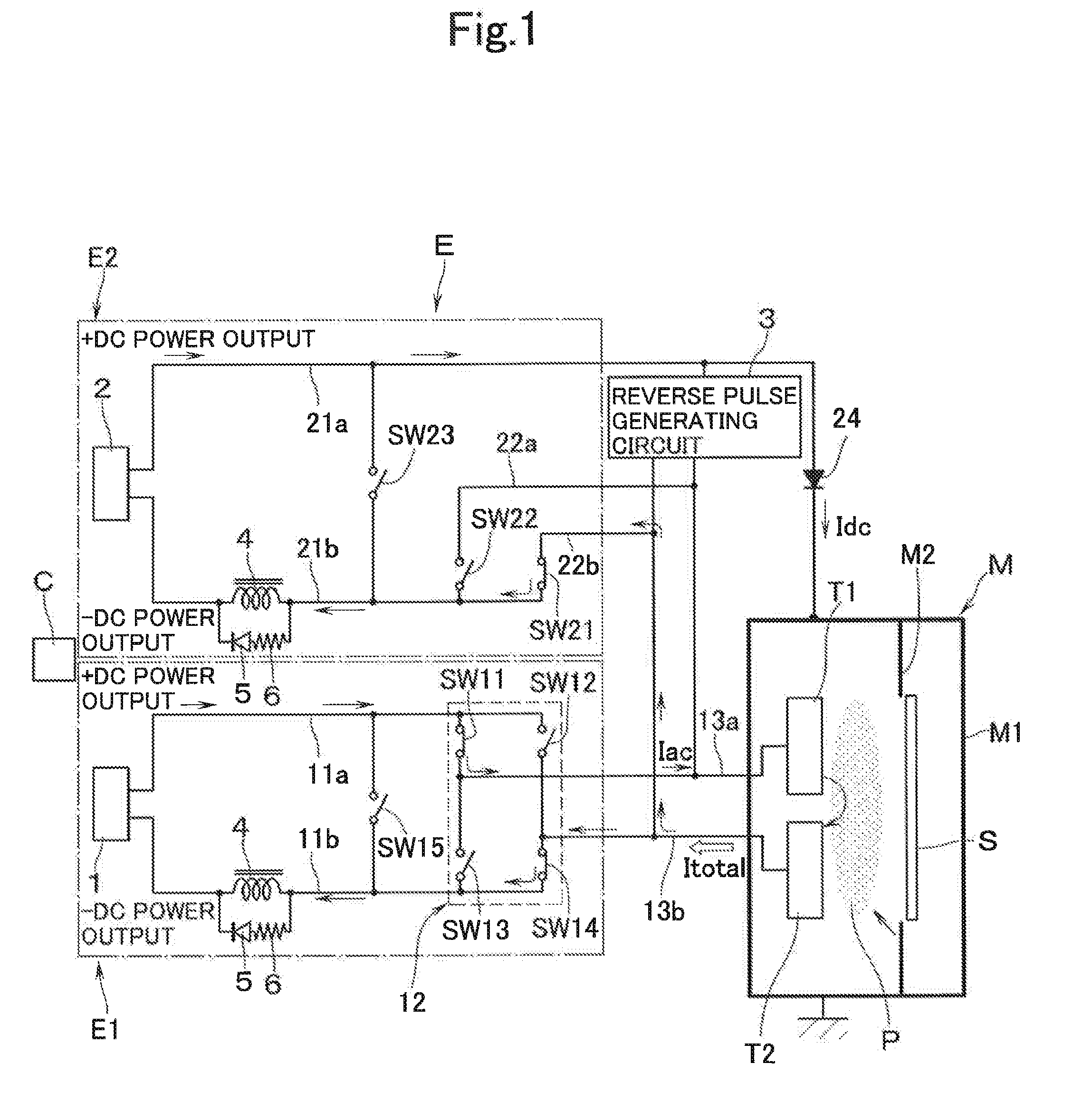
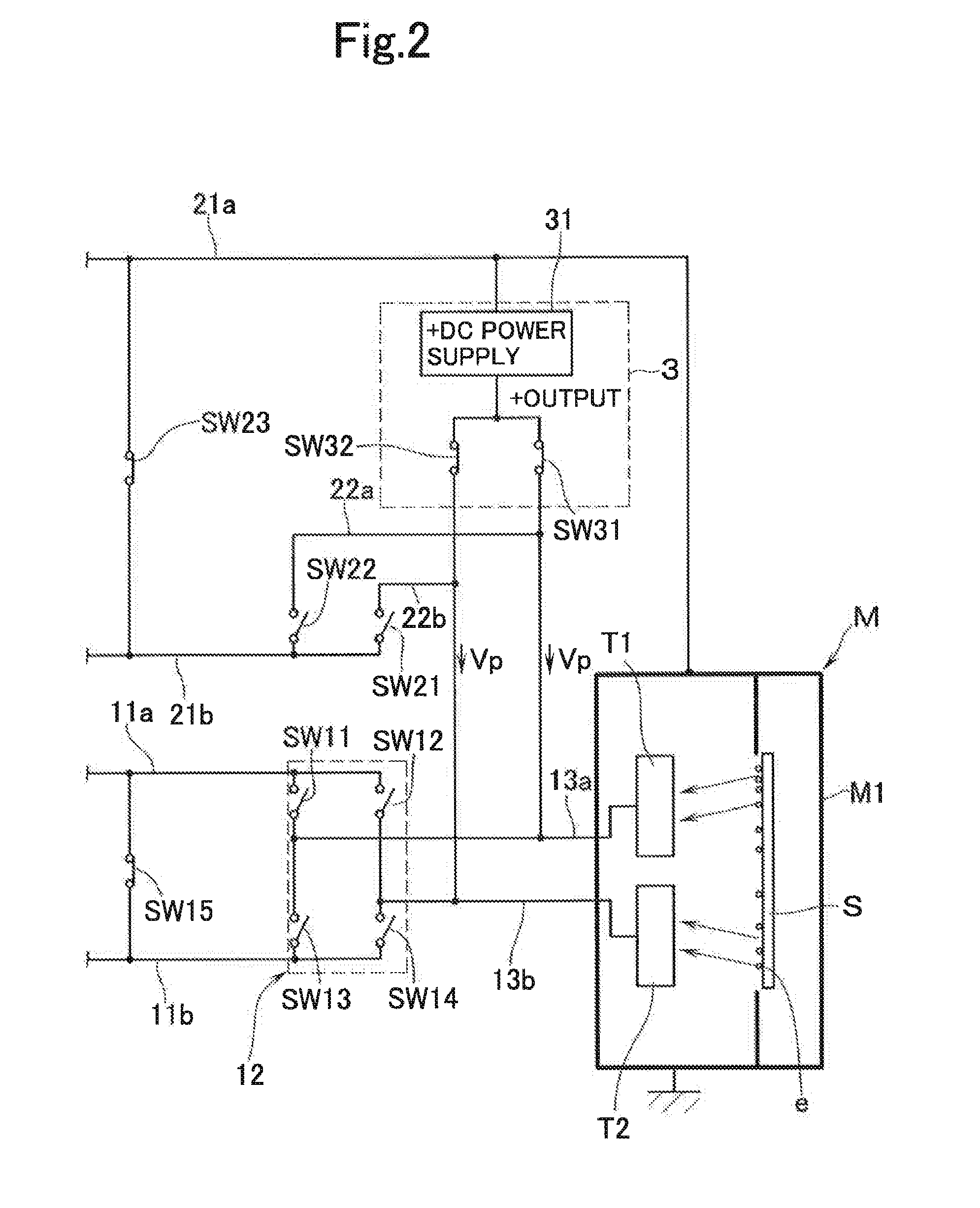
[0016]With reference to the accompanying drawings a description will now be made of a power supply apparatus E according to an embodiment of this invention. The power supply apparatus E is used to charge (or gives an output to) a pair of targets T1, T2, which serve as electrodes in contact with a plasma P, with AC pulsed potential at a predetermined frequency, the targets being disposed opposite to a substrate S which is present inside a vacuum chamber (processing chamber) M1, e.g., of a sputtering apparatus M. The power supply apparatus E has: a first discharge circuit E1 and a second discharge circuit E2; and a control means C for making an overall control of the operation, and the like of switching elements (to be described hereinafter) which are disposed in the first discharge circuit E1 and the second discharge circuit E2 (see FIG. 1).

[0017]The first discharge circuit E1 has a DC power supply source 1 which enables the supply of DC power. Although not illustrated, the DC power ...


PUM

PropertyMeasurementUnit
Areaaaaaaaaaaa
Frequencyaaaaaaaaaa

Abstract

There is provided a power supply apparatus that is capable of suppressing the occurrence of anomalous electric discharge due to charge-up of a substrate and that is capable of forming a good thin film on a large-area substrate. The power supply apparatus of this invention has: a first discharge circuit that alternately charges predetermined potential at a predetermined frequency to a pair of targets that are in contact with a plasma; and a second discharge circuit that charges predetermined potential between the grounding and the electrode, out of the pair of electrodes, that is not charged with potential from the first discharge circuit. The second discharge circuit is provided with a reverse potential charging means for charging, at the time of polarity reversal, at least one of the electrodes with potential that is reverse to the output potential.

Description

TECHNICAL FIELD[0001]The present invention relates to a power supply apparatus and, in particular, to a power supply apparatus to be used in applying power to targets in a sputtering apparatus.BACKGROUND ART [0002]As a method of forming a predetermined thin film on a surface of a substrate to be processed such as glass or silicon wafer, there is known a sputtering method. The sputtering method is an art in which the ions in a plasma atmosphere are accelerated and collided onto targets which are formed into a predetermined shape depending on the composition of the thin film to be formed on the surface of the substrate, and in which the sputtered particles (atoms of the targets) are scattered for getting adhered and deposited on the surface of the substrate to thereby form a predetermined thin film. Recently the method is used, in the process of manufacturing a flat panel display (FPD), to form a thin film such as an ITO and the like on a large-area substrate.[0003]The following is kn...

Claims


Application Information

Patent Timeline
IPC IPC(8): C23C14/34
CPCC23C14/3464C23C14/542H05H1/46H01J37/3444H03H7/38H01J37/34H02M3/155
Inventor HORISHITA, YOSHIKUNIMATSUBARA, SHINOBUONO, ATSUSHI
Owner ULVAC INC
Why Eureka
Try Eureka