Temperature and low water monitoring for boiler systems

a technology for low water monitoring and boiler systems, applied in the field of safety devices, can solve the problems of not being able to replace the sensor of an existing aquastat, providing high temperature limit without provision to turn the burner, and reluctance to accommodate multiple tappings for water cutoff probes and temperature sensor probes

Inactive Publication Date: 2011-05-26
C COWLES
View PDF17 Cites 27 Cited by
  • Summary
  • Abstract
  • Description
  • Claims
  • Application Information

AI Technical Summary

Benefits of technology

[0017]It is yet another object of the present invention to provide a control unit that allows a user to set the limits for temperature and monitor low water conditions.
[0019]A further object of the present invention is to provide a safe condition when the dual probe sensor is connected to the control circuitry but not properly inserted within the well, which would otherwise cause a run-away boiler condition.

Problems solved by technology

This control, however, does not allow for the ability to replace the sensor of an existing aquastat such as the Honeywell devices described above without draining the boiler and possibly the entire heating system.
Furthermore, this design only provides high temperature limit with no provision to turn the burner on to maintain a minimum boiler temperature, or to control the circulator pump on a call for heat.
One problem in the industry has been the reluctance to accommodate multiple tappings for water cutoff probes and temperature sensor probes.
This requires expensive redesigns of boiler castings to accommodate a second hole in the boiler wall for the additional probe.
Another problem that occurs is when the control circuitry is set to maintain a minimum water temperature and the temperature sensor is not in the boiler.
In the prior art, the control circuitry would incorrectly determine that the water temperature is too low, and try to run the boiler, causing an unsafe, high temperature condition.

Method used


Image

  • Temperature and low water monitoring for boiler systems
  • Temperature and low water monitoring for boiler systems
  • Temperature and low water monitoring for boiler systems

Examples


Embodiment Construction

)

[0036]In describing the preferred embodiment of the present invention, reference will be made herein to FIGS. 1-9 of the drawings in which like numerals refer to like features of the invention.

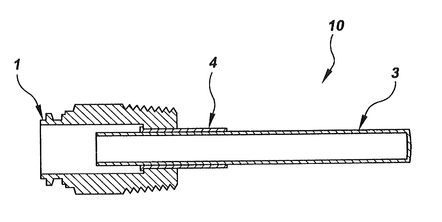
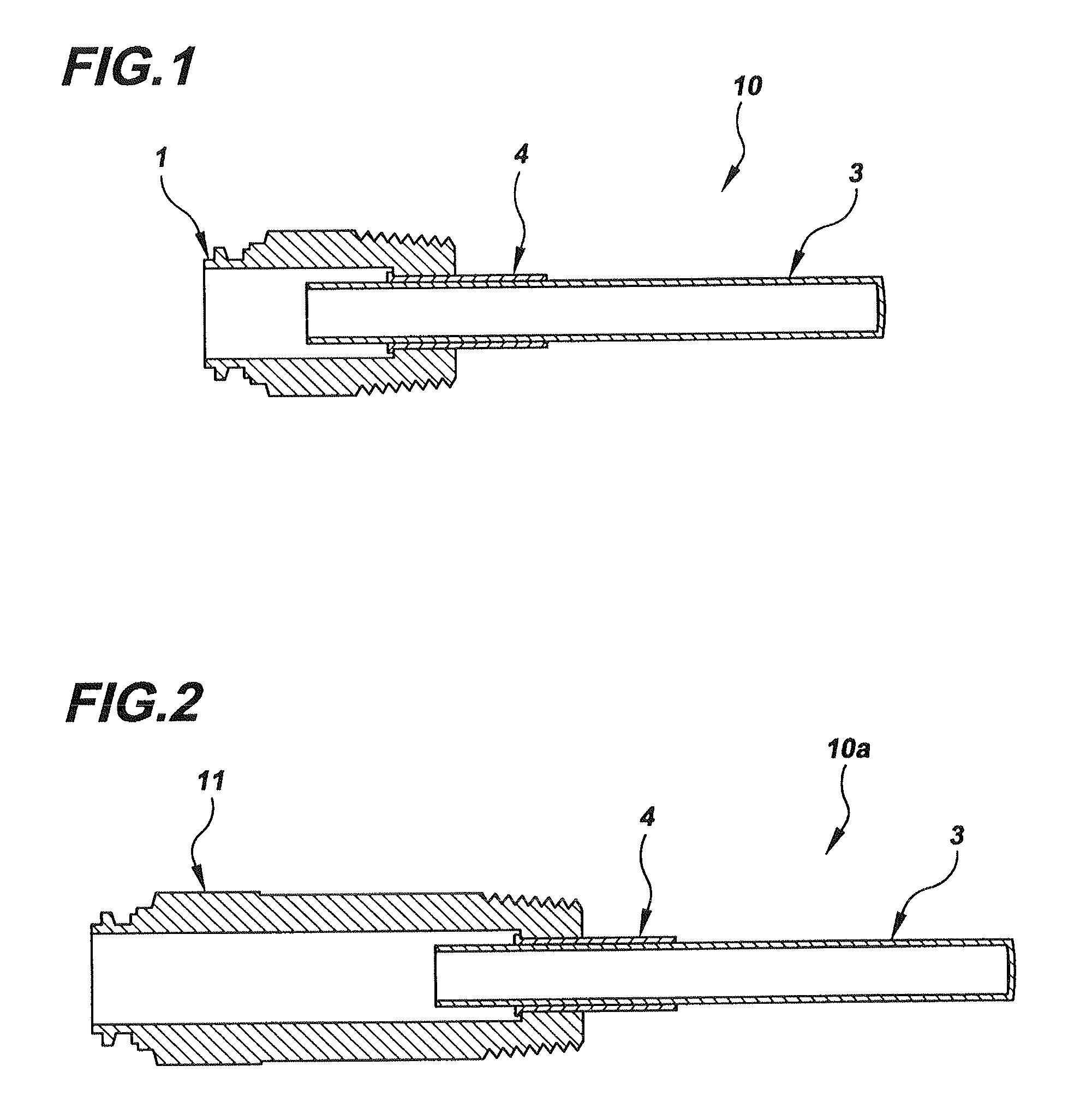
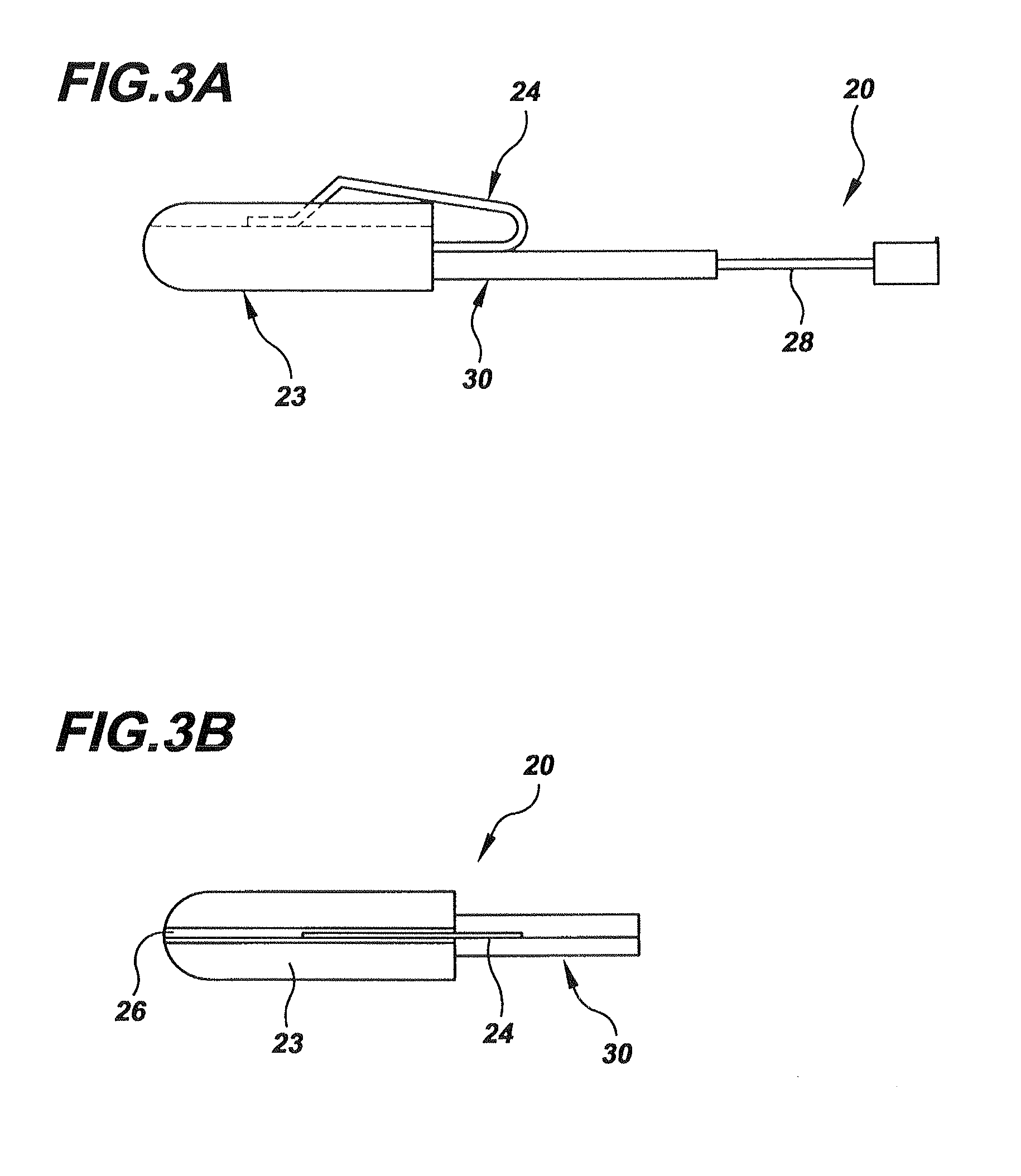
[0037]The present invention teaches a dual functionality of temperature control measurement and low water cut-off measurement within a single tapping in a boiler. This dual functionality combines a low water cut-off and temperature sensor into one control utilizing a sensing element suitable for use in an existing ¾″ tapping for typical boilers. The tappings generally comprise a threaded brass nut for insertion in a boiler housing wall, a hollow, cylindrical temperature / low water cut-off well for protecting and securing the sensors, and an insulator (dielectric), which electrically separates the brass nut from the cylindrical well. The sensor well allows a user to insert the temperature sensor and low water cutoff sensor without draining the system. Importantly, the sensor well may be used fo...


PUM

PropertyMeasurementUnit
resistanceaaaaaaaaaa
operating temperatureaaaaaaaaaa

Abstract

A dual functionality temperature control measurement and low water cut-off measurement system is taught within a single tapping to a boiler. This dual functionality combines a low water cut-off and temperature sensor into one control utilizing a sensing element suitable for use in a single existing tapping for a boiler. Independent of low water functionality, the temperature sensor is also capable of monitoring temperature as a replacement probe in an existing temperature sensor-only well. A conductive member provides a compression fit inside the probe well for thermistors, while simultaneously providing conduction with the well interior for a low water cutoff signal in a two-conductor well.

Description

[0001]This application is a Continuation application of patent application Ser. No. 11 / 697,063 filed Apr. 5, 2007.BACKGROUND OF THE INVENTION[0002]1. Field of the Invention[0003]The present invention relates to safety devices that automatically cut-off the burner operation of a hot water boiler. More specifically, the present invention relates to the type of boiler used in residential and light commercial heating applications that include a control system for monitoring both the temperature and level of the water in the boiler. The system allows these attributes to be measured through a single probe inserted into the boiler through a single tapping.[0004]2. Description of Related Art[0005]In conventional boilers of the type used in residential and light commercial heating the water level is monitored with a low water cutoff (LWCO) sensor. When the water level in the boiler drops below the level of the low water cutoff sensor, the burner is turned off until the water level is brought...

Claims


Application Information

Patent Timeline
Patent Type & Authority Applications(United States)
IPC IPC(8): G01K1/00
CPCF22B37/46F22B37/47B23P19/00Y10T29/4973G01F23/00G01K13/00G06K13/00F24H9/2007F24D19/1009F24H15/258F24H15/414F24H15/246F24H15/281F24H15/254F24H15/395F24H15/219F24H15/215
Inventor MURRAY, CHRISTOPHER L.
Owner C COWLES
Why Eureka
Try Eureka