
Metal powder for metal laser-sintering and metal laser-sintering process using the same

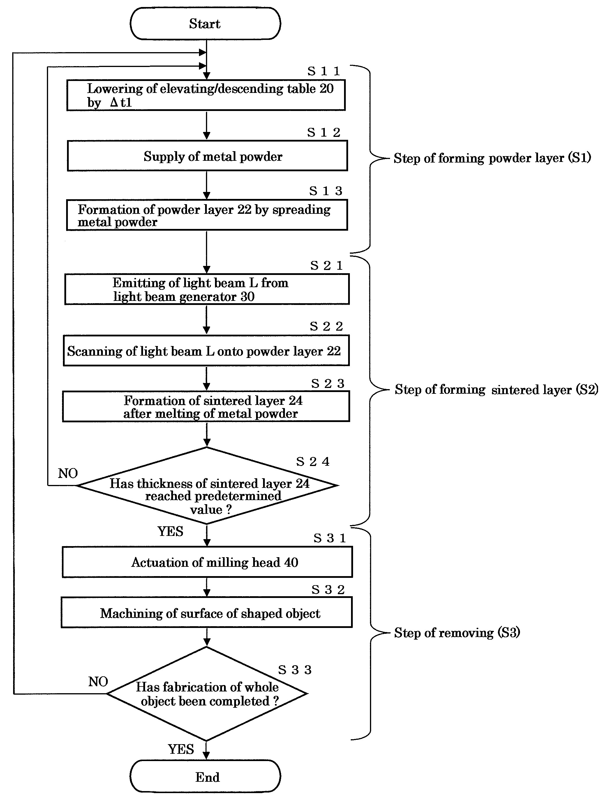
a metal laser sintering and metal laser sintering technology, applied in the field of metal powder, can solve the problems of inability to uniformly form a thin metal layer, formation of sintered materials, and inability to form such subsequent powder layers, so as to and reduce the machining resistance. effect of unnecessary removal of metal powder

Inactive Publication Date: 2011-05-26
PANASONIC CORP
View PDF10 Cites 69 Cited by
  • Summary
  • Abstract
  • Description
  • Claims
  • Application Information

AI Technical Summary

Benefits of technology

[0012]The present invention is directed to solve the above problem. In other words, an object of the present invention is to provide a metal powder for metal laser-sintering, making it possible to reduce a machining resistance that is provided upon the removing operation of the residual metal powder adherent to the surface of the shaped object, thereby extending the lifetime of the machining tool.Means for Solving the Problems
[0018]In the metal powder for metal laser-sintering of the present invention, the iron-based powder is in a soften state due to the annealing treatment thereof. This softness can reduce a machining resistance which is attributable to the residual metal powder adherent to the surface of the shaped object obtained by the metal laser-sintering. In other words, the machining resistance upon removing an unnecessary metal powder attached to the surface of the shaped object by machining the surface thereof can be reduced, which leads to an achievement of the lifetime extension of the machining tool that is used for such removing. The phrase “machining tool” used herein means a machining tool commonly used for the metal laser-sintering process.
[0021]In accordance with the present invention, even in a case where an atomized powder having a relatively high hardness is used as the iron-based powder, such powder has been annealed so that it is in a softened state. Consequently, the softened state of the atomized iron-based powder can reduce the machining resistance that is attributable to the residual metal powder adherent to the surface of the shaped object obtained by the metal laser-sintering. In other words, in a case where the atomized powder having a relatively high hardness is used as a raw material for the metal laser-sintering, it is possible to extend the lifetime (service time) of the machining tool which is used for removing an unnecessary metal powder adherent to the surface of the shaped object.

Problems solved by technology

On the other hand, when the particle diameter is too small, the metal powder tends to form the aggregated particles so that a packing density of the powder becomes lower, thus making it impossible to uniformly form a thin metal layer thereof.
The bulge with more than the thickness of the powder layer can interfere with the spread of the subsequent powder layer, making it impossible to form such subsequent powder layer.
This results in a formation of a sintered material.
There is a possibility that the three-dimensional shaped object produced by the metal laser-sintering process has the residual metal powder adherent to the surface thereof, resulting in a rough surface of the object.
When the metal laser-sintering process is carried out by using a metal powder containing an iron-based powder with high hardness, the edge of the machining tool may wear out due to the hardness of the iron-based powder during the machining operation.
Particularly when a narrow groove of the object is machined, it is required to use a machining tool having smaller diameter that is more prone to wear out and may undergo a chipping or breakage.
However, even the metal powders for metal laser-sintering described in Japanese Unexamined Patent Publications (Kokai) Nos. 2001-152204 and 2004-277877 have such problem that the hard iron-based powder adherent to the surface of the shaped object produced by the metal laser-sintering process causes a machinability resistance to be increased upon the finish machining of the surface, which leads to a short lifetime of the machining tool.
On the other hand, a slower machining rate is required for extending the lifetime of the tool, resulting in an increase of the necessary time for machining operation.

Method used


Image

  • Metal powder for metal laser-sintering and metal laser-sintering process using the same
  • Metal powder for metal laser-sintering and metal laser-sintering process using the same
  • Metal powder for metal laser-sintering and metal laser-sintering process using the same

Examples


examples

[0080]An annealing treatment of an iron-based powder used as a raw powder of the metal powder for metal-laser sintering was performed. In this treatment, the annealing conditions were studied for the following reasons:[0081]When the iron-based powder is heated, the surfaces of powder particles are activated, and thus mutual contacting portions of such particles turn into more stable shape. Namely, the metal atoms of the particles are caused to move in such directions that the surface area of the particles becomes smaller, and thereby there is occurred a sintering phenomenon allowing the powder particles to unite with each other. The smaller particle diameter of the powder provides the larger surface area of the powder, causing the sintering phenomenon to proceed at a lower temperature due to a larger contacting surface between the particles. Also, a higher temperature of the heating induces an occurrence of the sintering phenomenon. Accordingly, in a case of the powder with a large ...


PUM

PropertyMeasurementUnit
mean particle diameteraaaaaaaaaa
temperatureaaaaaaaaaa

Abstract

A metal powder for use in a metal laser-sintering wherein a three-dimensional shaped object is produced by irradiating a powder layer of the metal powder with a light beam to form a sintered layer and thereby laminating the sintered layers. The metal powder of the present invention is characterized in that it comprises an iron-based powder and at least one kind of powder selected from the group consisting of a nickel powder, a nickel-based alloy powder, a copper powder, a copper-based alloy powder and a graphite powder; and the iron-based powder has been annealed. In such metal powder, the iron-based powder is in a softened state due to the annealing treatment thereof. Accordingly, the use of the metal powder in a metal laser-sintering process makes it possible to reduce a machining resistance attributable to the residual metal powder adherent to the surface of the shaped object, which leads to an achievement of an extended lifetime of a machining tool.

Description

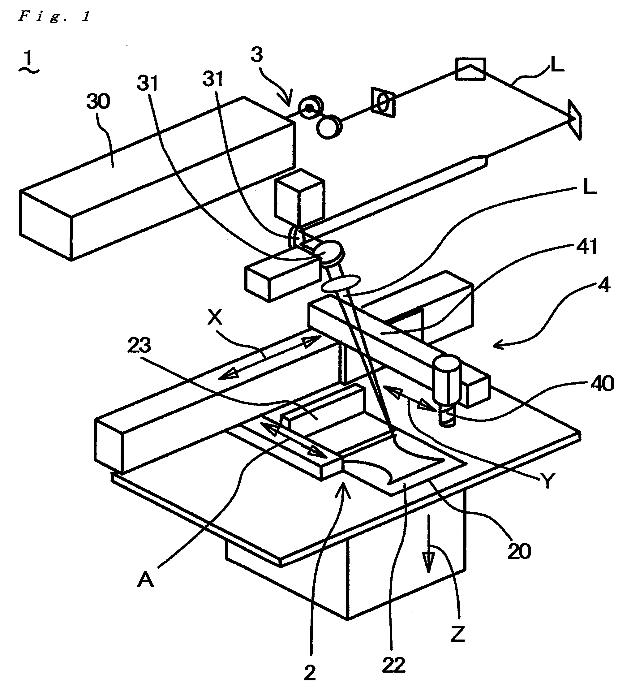
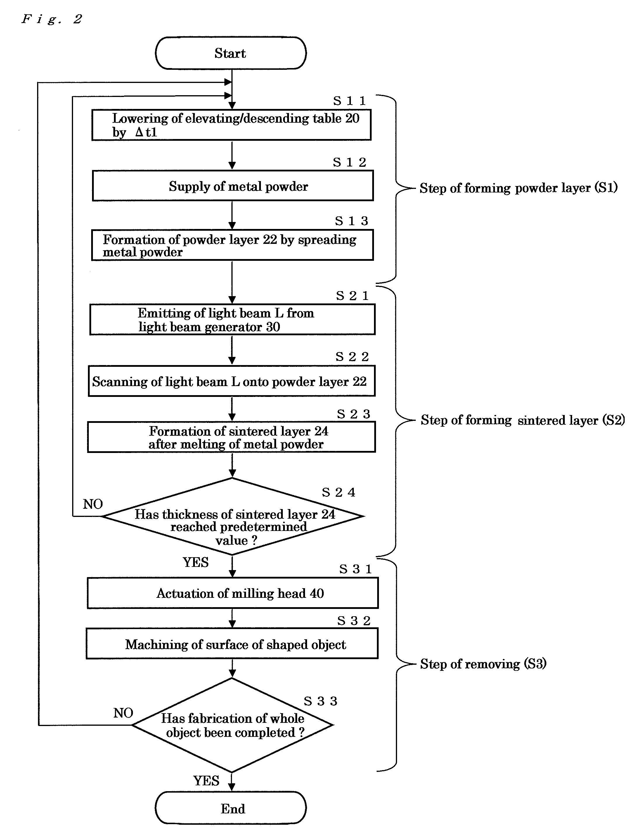
TECHNICAL FIELD[0001]The present invention relates to a metal powder used in a metal laser-sintering process. More particularly, the present invention relates to the metal powder used in the metal laser-sintering process wherein a three-dimensional shaped object is produced by a light beam irradiation.BACKGROUND OF THE INVENTION[0002]A metal laser-sintering technology has been known as a means for manufacturing a three-dimensional shaped object wherein the shaped object is obtained by repeating steps of (1) irradiating a powder layer of a metal powder with a light beam (e.g. directional energy beam such as laser beam) to form a sintered layer and (2) providing another powder layer on the sintered layer thus formed and irradiating it with the light beam to form another sintered layer. This technology makes it possible to manufacture the three-dimensional shaped object with a complicated profile in a short period of time. Particularly when a sufficient melting of the metal powder occu...

Claims


Application Information

Patent Timeline
Patent Type & Authority Applications(United States)
IPC IPC(8): C22C33/02C22C30/02C22C30/00B22F1/12
CPCB22F3/1055B22F2998/00B22F1/0085B22F2999/00B22F2998/10B33Y70/00B33Y10/00Y02P10/25B22F10/28B22F12/44B22F12/49B22F10/66B22F12/41B33Y40/10B33Y40/20B22F1/12B22F3/16B22F2003/247B22F1/142B22F3/10B22F3/105
Inventor FUWA, ISAOABE, SATOSHI
Owner PANASONIC CORP
Learn More