

Composition and system for preformed thermoplastic road marking with sequential features
- Summary
- Abstract
- Description
- Claims
- Application Information
AI Technical Summary
Benefits of technology
Problems solved by technology
Method used
Image

Examples
Embodiment Construction
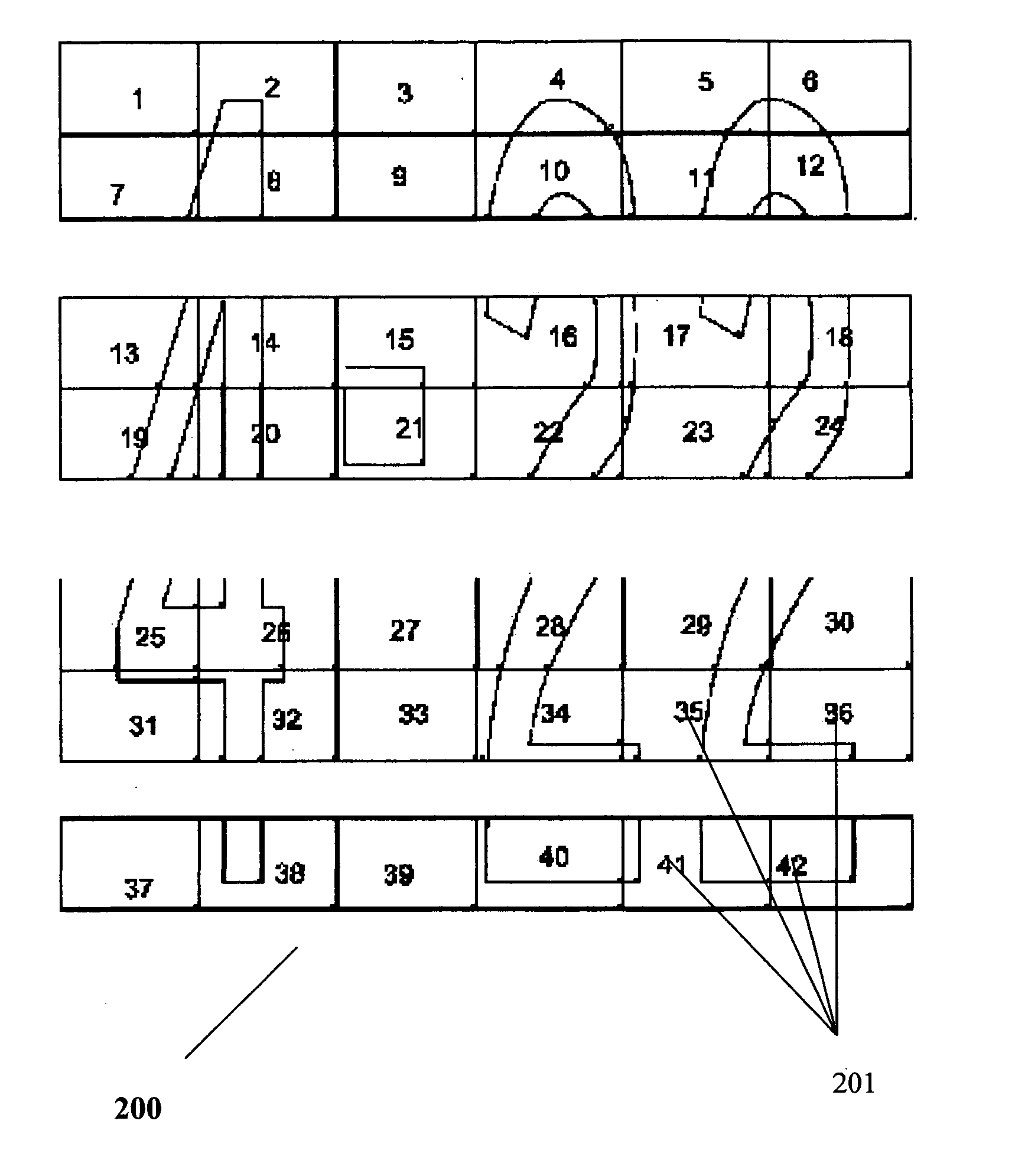
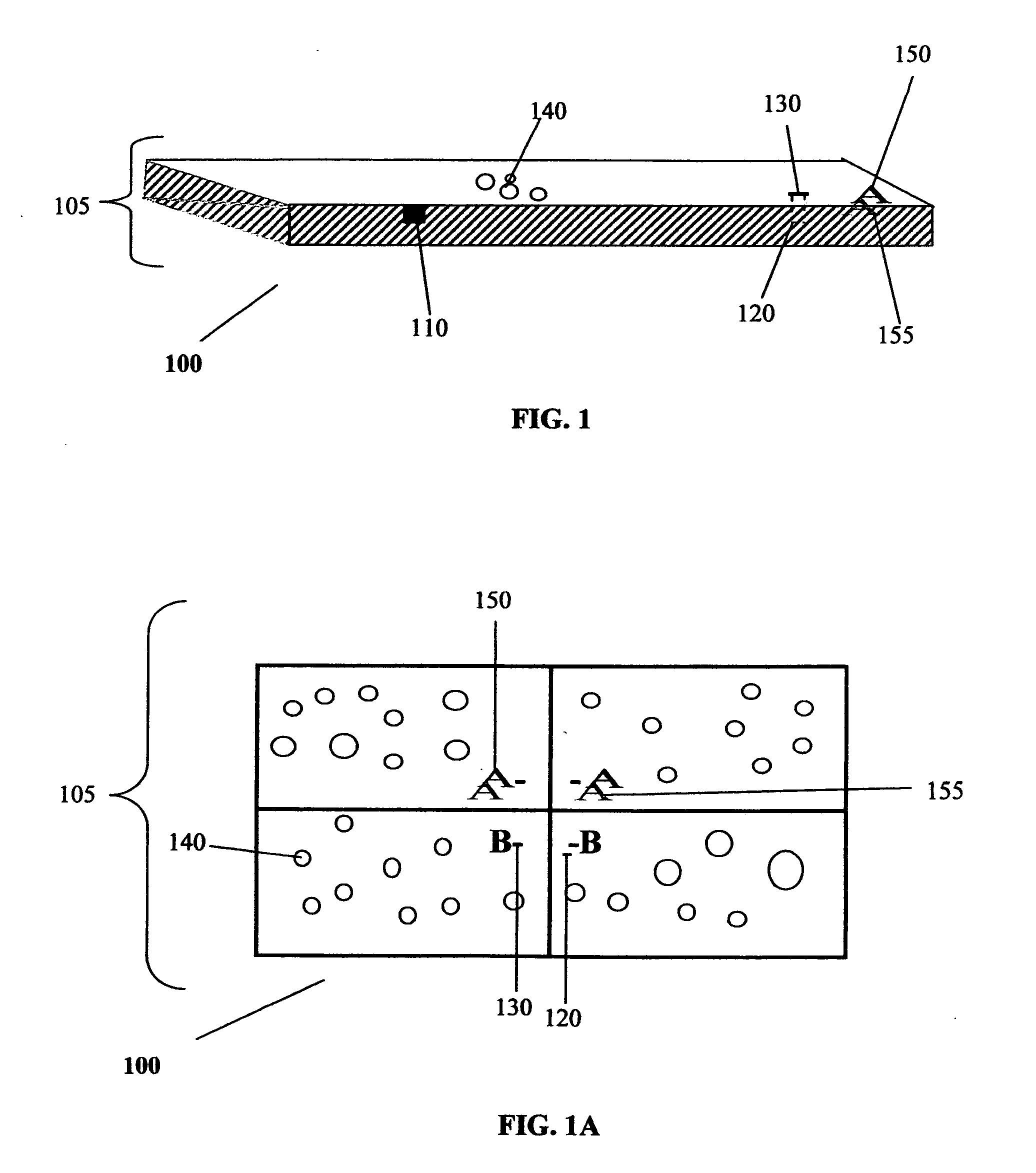
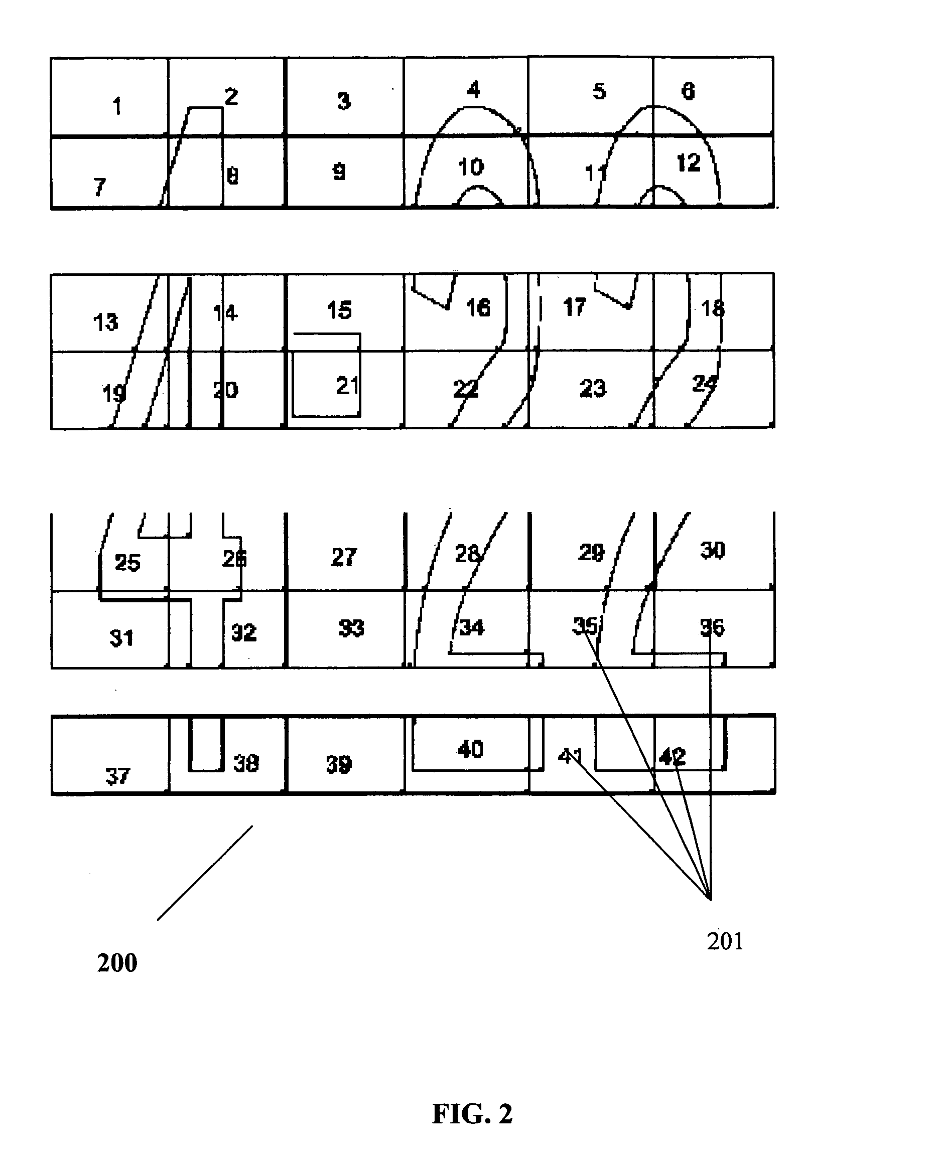
[0072]The present disclosure relates to a method for adhering preformed thermoplastic signage markings (e.g. for pavement substrates) that contain features such as an indent, dimple, bump, sequential alphanumeric slits or other markers that are provided on the surface of alkyd thermoplastic compositions (generally known as thermoplastic signage) to traffic surfaces to provide permanent pedestrian and traffic control markings.
[0073]A representative example of the composition of these preformed thermoplastic sections or rolls is given below:[0074]Polyamide, Unirez 2633, Arizona Chemical 8%[0075]Wax, Clarient PE-520 2%[0076]Plasticizer, DINP di-isononyl phthalate 4%[0077]Tackifier Resin, Sylvacote 7021, Arizona Chemical 8.5%[0078]Fumed silica, Cabot TS-720, 1%[0079]Calcium Carbonate, 36.5%[0080]AASHTO Type 1 intermix beads, 30%[0081]Titanium Dioxide, 10%
[0082]Heating of the surface of the thermoplastic signage may be accomplished by a heating means such as a propane-fueled infrared hea...
PUM
| Property | Measurement | Unit |
|---|---|---|
| Fraction | aaaaa | aaaaa |
| Fraction | aaaaa | aaaaa |
| Fraction | aaaaa | aaaaa |
Abstract
Description
Claims
Application Information