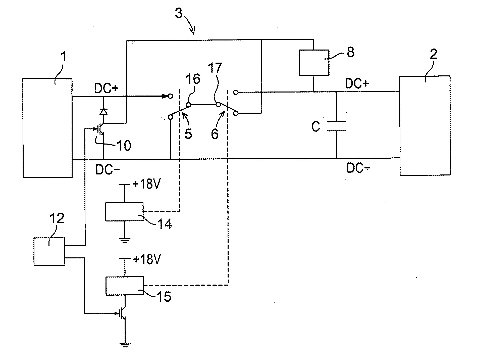
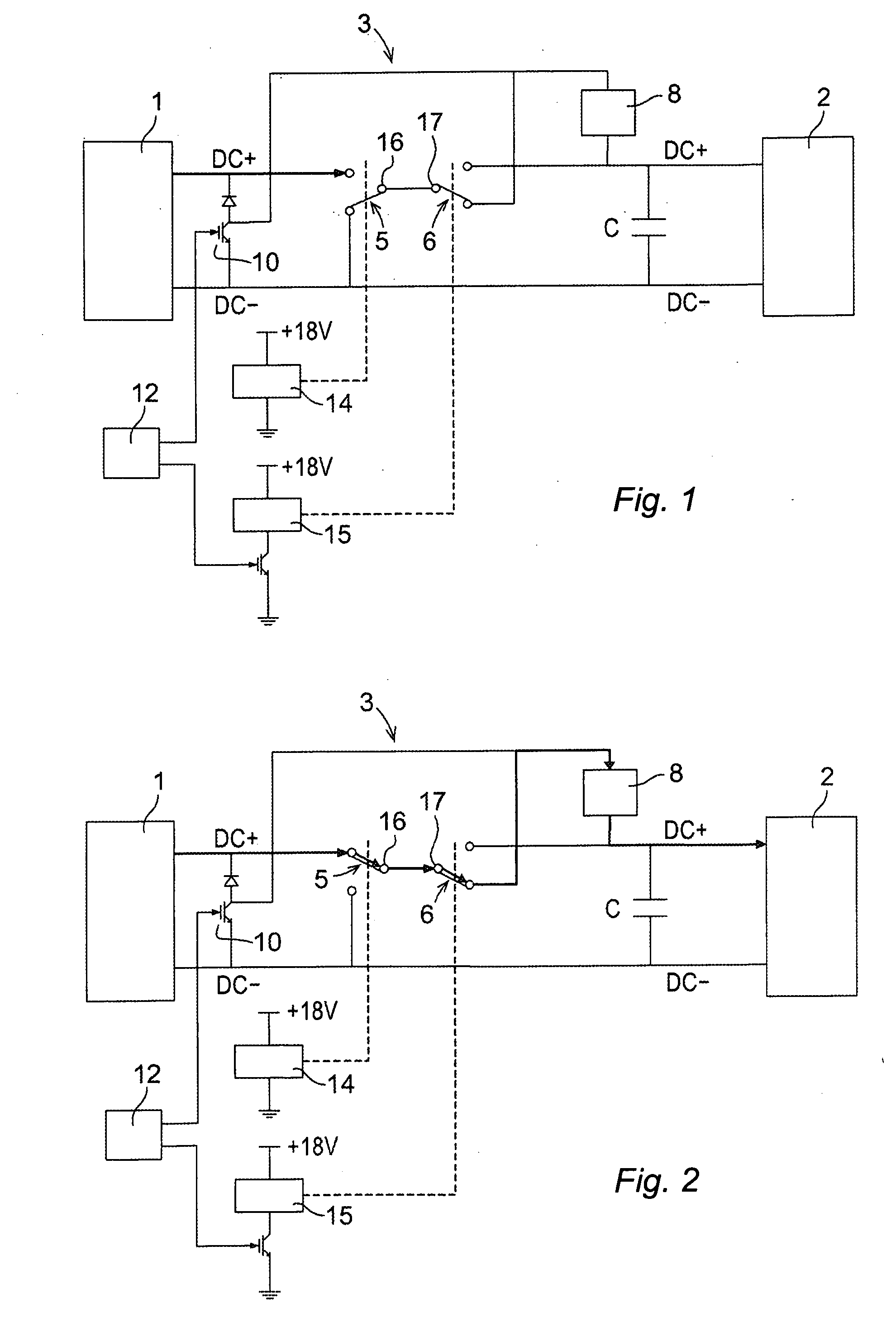
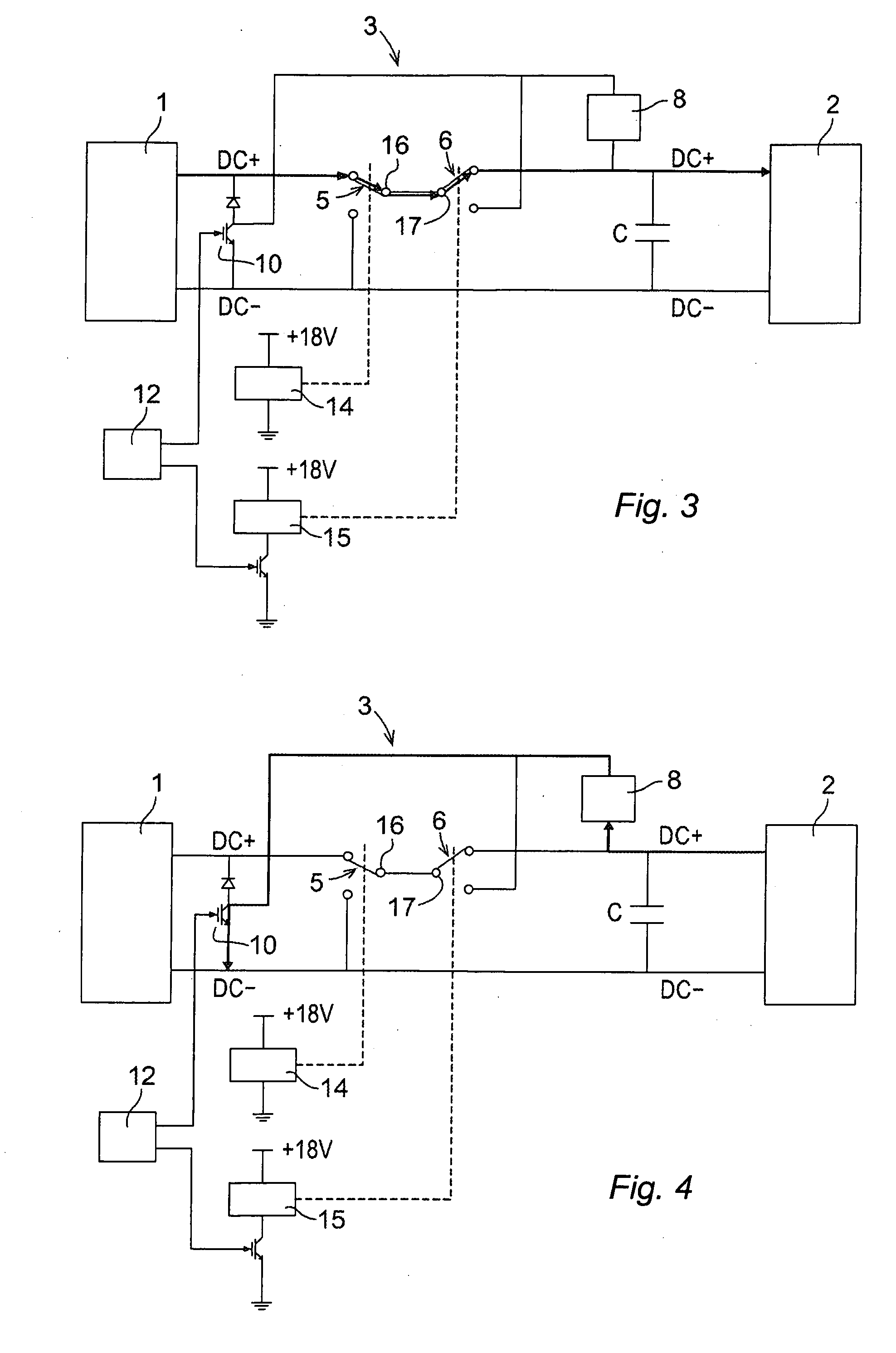
[0014]According to the invention, the same power resistor that is used for discharging the energy storage if the
voltage across the energy storage becomes too high during operation of the drive unit, is used for discharging the
capacitor when control power is lost or turned off. Two switches are used to control the
charge and discharge of the energy storage of the drive unit, together with the power resistor of the discharge circuit. The two switches automatically switch back to their default positions when the control power in the drive unit is taken away, on purpose or by accident, and the drive unit is arranged such that the energy storage is discharged via the power resistor of the discharge circuit when the switches are in their default positions. The present invention enables the
capacitor to be discharged quickly, such as within 5 seconds, even in a worst case when the control power is lost by accident. A further
advantage of the present invention is that no separate power resistor is needed to discharge the capacitor after control power has been removed and operation of the drive unit has been stopped. This saves costs and size since the power resistor has to be large in order to make the
charge and discharge time short.
[0015]Further, the power supply to the motor is automatically turned off when the control power in the drive unit is turned off, or lost by accident. This is achieved due to the features that the drive unit is arranged such that the power source is disconnected from the motor when the switches are in their default positions, and the two switches automatically switch back to their default positions when the control power in the drive unit is taken away. Thus, another
advantage with the present invention is that it prevents transfer of power from the power source to the motor at a point in time when there is no control power in the drive unit, such as when the control power has been deliberately turned off, or when the control power has been lost by accident. This is important since it is very dangerous to let the main power go to the motor without control power. It can be dangerous to humans since the
DC bus voltage can already have built up several hundred volts in a traditional design. For instance, there should be no main power and no control power in the drive unit before the drive unit is powered on.
[0016]According to an embodiment of the invention, the first switch is controlled by the control power of the drive unit and is arranged to switch to the default position when there is no control power in the drive unit, and to switch to an engaged position when there is control power in the drive unit. The first switch is only controlled by the existence of control power. The switch will always be in its engaged position when there is control power in the drive unit, since there is no other
control signal that is used to control the first switch. The drive unit is arranged such that the power source is connected when the first switch is in the engaged position. The functions of the first switch is to ensure that the main power is immediately turned off when there is no control power in the drive unit and together with the second switch provide a quick discharge of the energy storage when the control power is removed.
[0017]According to an embodiment of the invention, the first switch is a
relay including a coil. The
relay is arranged such that current will go through the coil and engage the
relay when there is control power in the drive unit, and the relay will switch back to the default position when the control power is off. To use a relay as the switch is advantageous since a relay always switches back to its default position when the control power to the relay is turned off. Thus, the use of a relay increases the safety.
[0018]According to an embodiment of the invention, the drive unit further comprises a frequency inverter arranged to convert the direct current from the power source to a variable
alternating current for the motor, and a DC
bus for transferring the direct current from the power source to the inverter, the DC
bus comprising said energy storage, said discharge circuit and said first and second switches. The drive unit is arranged such that the power source is supplying current to the inverter when the first switch is in the engaged position, and the power supply to the inverter is disconnected when the first switch is in the default position. This feature is important since it can be dangerous to supply main power to the inverter without control power to the DC bus.
[0019]According to an embodiment of the invention, the second switch is controlled by a
control signal, the drive unit comprises a
control unit configured to generate said
control signal, and the second switch is configured to switch to the default position when there is no control power in the drive unit, or the control
signal commands switching to the default position, and to switch to an engaged position when there is control power in the drive unit, and accordingly in the DC bus, and the control
signal commands switching to the engaged position. When there is control power in the drive unit it is possible to move the switch between the default position and the engaged position. The drive unit is arranged so that the energy storage is charged via the power resistor when the second switch is in its default position and the energy storage is charged, but not via the power resistor, when the second switch is in its engaged position. Accordingly, the functions of the second switch is to switch between charging the energy storage via the power resistor and charging the energy storage directly from the power source, and, together with the first switch, provide a quick discharge of the energy storage when the control power is removed. The power resistor of the discharge circuit is used for both the charging and the discharging of the capacitor.


