

Delay Compensated Air/Fuel Control of an Internal Combustion Engine of a Vehicle
a technology of internal combustion engine and delay compensation, which is applied in the direction of electrical control, process and machine control, etc., can solve the problems of limiting the ability to properly regulate aggressive modulation of exhaust feed gas, low gain feedback control with sluggish response speed, and hindered closed loop fuel/air control using the uego sensor. the effect of response speed and accuracy
- Summary
- Abstract
- Description
- Claims
- Application Information
AI Technical Summary
Benefits of technology
Problems solved by technology
Method used
Image

Examples
Embodiment Construction
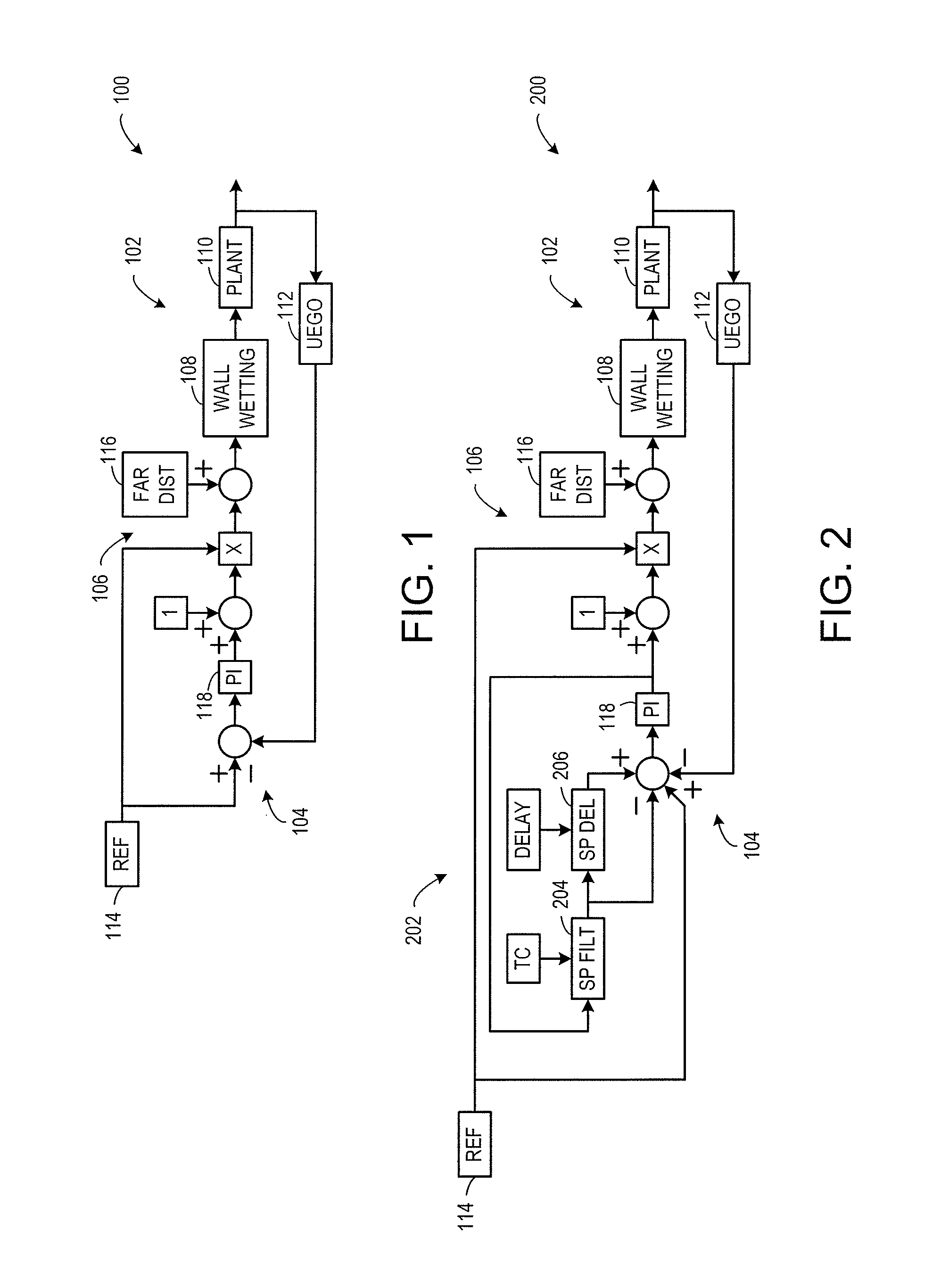
[0018]FIG. 1 shows a closed loop fuel control system 100 (referred to herein as “control system”) that operates based on feedback from a linear or universal exhaust gas oxygen (UEGO) sensor without compensating for a response delay of the UEGO sensor. The control system 100 varies fuel / air ratio based on operating conditions. A reference source 114 generates a desired signal at the input of control system 100 that is adjusted by various intermediate control blocks to provide a desired fuel control signal to a plant block 110 at the output of the control system. The desired fuel signal may be generated by the reference source based on the desired fuel / air ratio, which another part of the control system determines, to optimize emissions, fuel economy, and drivability. In these figures, the reference is assumed to be normalized fuel / air ratio, i.e. will be a value of 1 when the fuel and air inducted into the combustion cylinders has exactly enough fuel and oxygen to burn without any le...
PUM
 Abstract
Description
Claims
Application Information