
Operating an engine with reformate

a technology of engine and reformer, which is applied in the direction of machines/engines, electric control, instruments, etc., can solve the problems of engine misfire, increased emissions or less efficient engine combustion, and achieve the effects of improving combustion stability, heating value, and knock resistan

Inactive Publication Date: 2011-06-09
FORD GLOBAL TECH LLC
View PDF63 Cites 54 Cited by
  • Summary
  • Abstract
  • Description
  • Claims
  • Application Information

AI Technical Summary

Benefits of technology

[0002]A reformer may convert a liquid fuel such as gasoline, diesel fuel, ethanol, etc. into a reformate gas so that the reformate gas can be combusted by an engine to improve combustion stability, knock resistance, and heating value. Further, reformed fuel may be used to purge or reduce constituents held or stored by an exhaust gas after treatment device. In one example, a reformate system may include a buffer tank, cooler, vaporizer, storage vessel, and gaseous injector to facilitate reformate use by a vehicle engine.
[0004]One advantage of the above method is that consequences of reformate system degradation may be reduced by limiting use of the reformate system after degradation is detected. For example, if the reformate system is providing less than a threshold amount of reformate, reformer operation can be limited so that less energy is consumed by operating the reformer and so that the engine does not continue to operate as if a higher amount of reformate is available. Further, by adjusting liquid fuel supplied to an engine as well as engine constituents (e.g., charge dilution and / or boost) reasonable engine performance may be maintained. In this way, engine operation may be maintained at a reasonable level.

Problems solved by technology

For example, as the number and complexity of components in a reformate system increases, an engine may need to operate under conditions both with and without reformate.
In one example, a low supply of reformate gas could result in engine misfire.
In a further example, a degradation of a reformate system component may lead to increased emissions or less efficient engine combustion.
For example, if the reformate system is providing less than a threshold amount of reformate, reformer operation can be limited so that less energy is consumed by operating the reformer and so that the engine does not continue to operate as if a higher amount of reformate is available.

Method used


Image

  • Operating an engine with reformate
  • Operating an engine with reformate
  • Operating an engine with reformate

Examples


Embodiment Construction

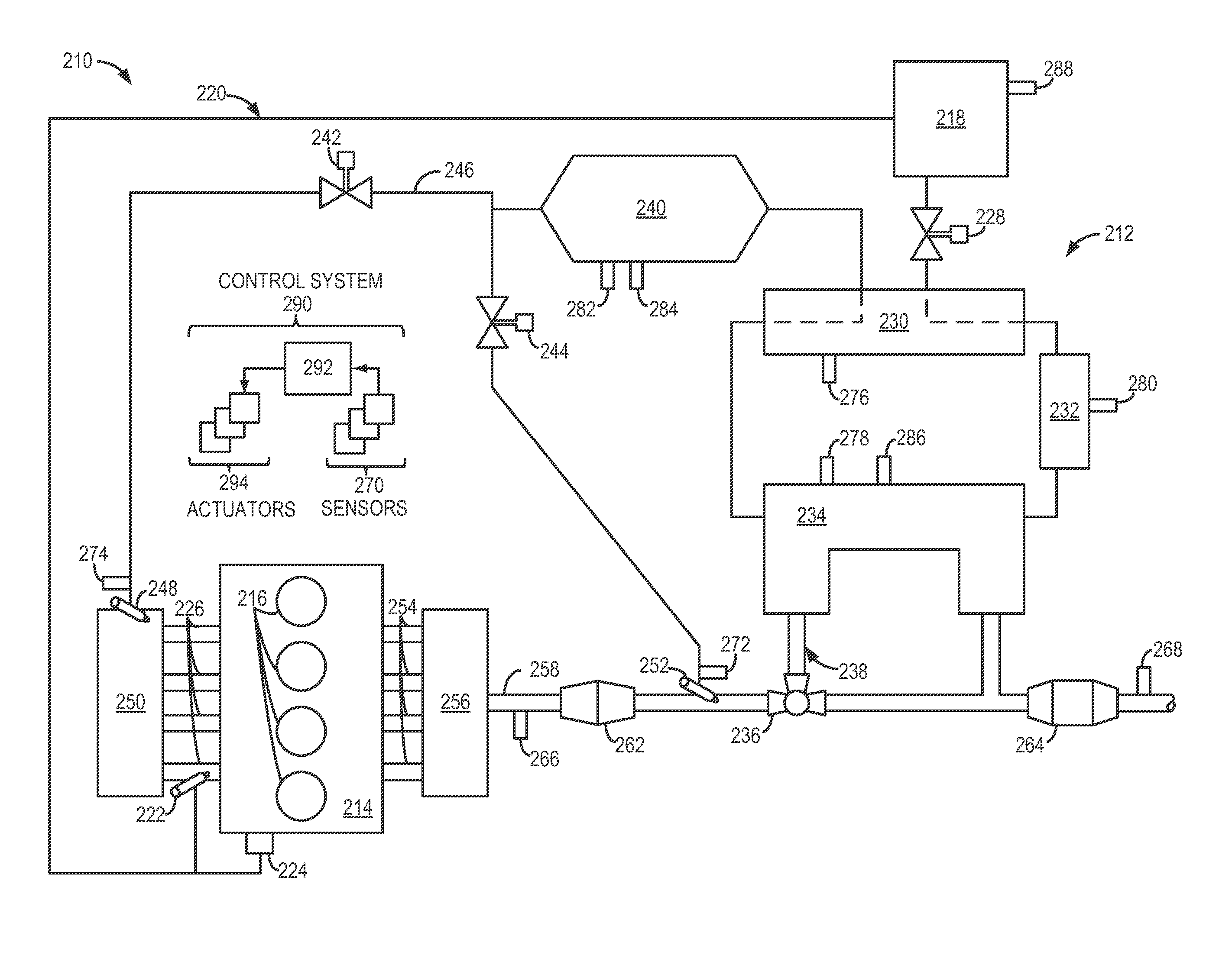
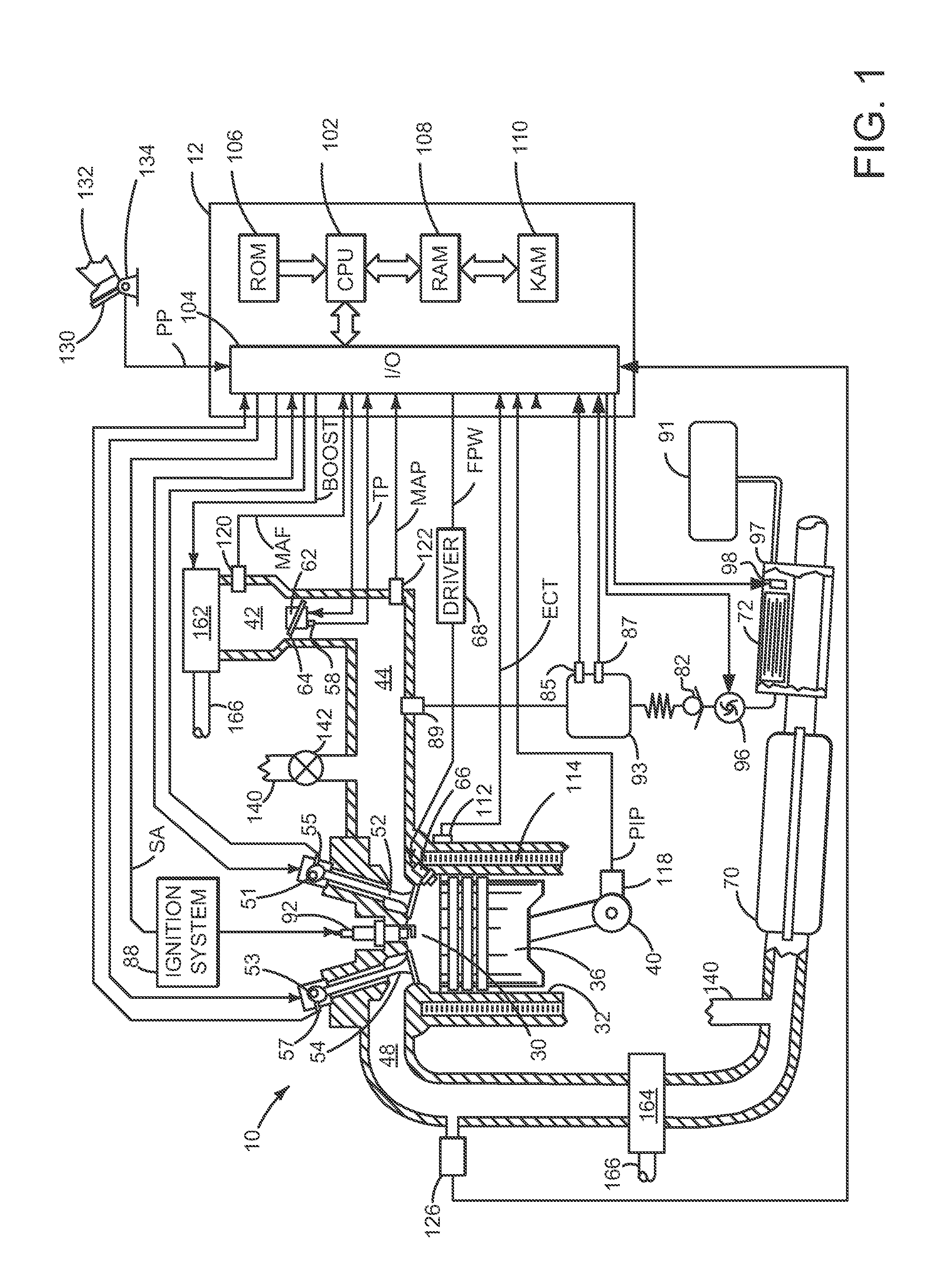
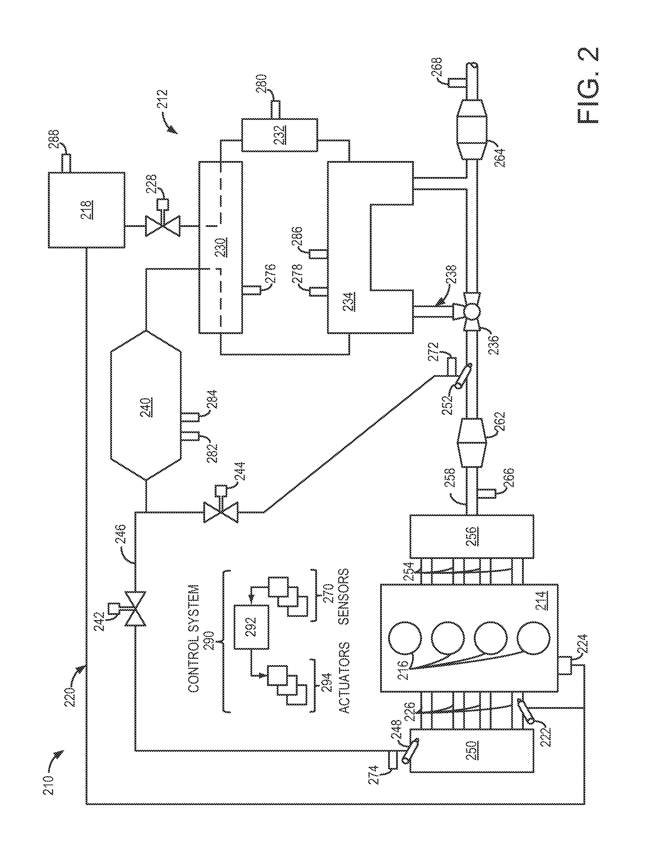
[0013]Devices, systems and methods are described herein, including detection modes for an example engine equipped with a reformer. First, example engines including reformate systems are shown in FIGS. 1 and 2. Then exemplary routines are described with reference to FIGS. 3-7 as example methods for control of such engines.

[0014]Turning to FIG. 1, internal combustion engine 10, comprising a plurality of cylinders, one cylinder of which is shown in FIG. 1, is controlled by electronic engine controller 12. Engine 10 includes combustion chamber 30 and cylinder walls 32 with piston 36 positioned therein and connected to crankshaft 40. Combustion chamber 30 is shown communicating with intake manifold 44 and exhaust manifold 48 via respective intake valve 52 and exhaust valve 54. Each intake and exhaust valve may be operated by an intake cam 51 and an exhaust cam 53. Alternatively, one or more of the intake and exhaust valves may be operated by an electromechanically controlled valve coil a...


PUM


Abstract

The present description relates to operation and control of a fuel reformer. In one embodiment, an engine constituent is adjusted in response to limiting an amount of reformate supplied to the engine during a condition of reformer degradation. The approach can improve engine operation.

Description

TECHNICAL FIELD[0001]The present application relates to control and management of engine systems including and related to a fuel reformer.BACKGROUND AND SUMMARY[0002]A reformer may convert a liquid fuel such as gasoline, diesel fuel, ethanol, etc. into a reformate gas so that the reformate gas can be combusted by an engine to improve combustion stability, knock resistance, and heating value. Further, reformed fuel may be used to purge or reduce constituents held or stored by an exhaust gas after treatment device. In one example, a reformate system may include a buffer tank, cooler, vaporizer, storage vessel, and gaseous injector to facilitate reformate use by a vehicle engine.[0003]The inventor herein recognizes various issues that may develop with engine and reformate systems. For example, as the number and complexity of components in a reformate system increases, an engine may need to operate under conditions both with and without reformate. In an engine designed to utilize reform...

Claims


Application Information

Patent Timeline
IPC IPC(8): F02D41/00F02B43/00F23C1/08
CPCF02D41/0027F02D41/3094F02D2200/0802Y02T10/36F02D19/0628F02D19/0671F02D19/081F02D19/0605Y02T10/30
Inventor LEONE, THOMAS G.
Owner FORD GLOBAL TECH LLC
Learn More