
Fluoride Ion Battery Electrolyte Compositions

Active Publication Date: 2011-06-16
CALIFORNIA INST OF TECH
View PDF6 Cites 56 Cited by
  • Summary
  • Abstract
  • Description
  • Claims
  • Application Information

AI Technical Summary

Benefits of technology

[0004]However, the electrochemistry of lithium metal or lithium containing electrodes presents problems for commercial use. Lithium metal is highly reactive, and substantial extra processing may be needed to store lithium in safer intercalate, forms, increasing battery weight and reducing energy density. Li-ion batteries are not stable in many situations, and can be easily overheated or overcharged. In extreme cases, this can result in thermal runaway and battery cell rupture, or short circuiting between the electrodes. For safety and to allow for high cycle lifetime, lithium-ion battery packs often contain expensive voltage and thermal control circuitry to shut down the battery when voltage or temperature is outside a safe range.

Problems solved by technology

However, the electrochemistry of lithium metal or lithium containing electrodes presents problems for commercial use.
Li-ion batteries are not stable in many situations, and can be easily overheated or overcharged.
In extreme cases, this can result in thermal runaway and battery cell rupture, or short circuiting between the electrodes.
For safety and to allow for high cycle lifetime, lithium-ion battery packs often contain expensive voltage and thermal control circuitry to shut down the battery when voltage or temperature is outside a safe range.
However, for many applications the discussed electrolyte compositions are not lithium-free or do not provide sufficient ion transport capability to ensure reliable, high discharge capacity operation.

Method used


Image

  • Fluoride Ion Battery Electrolyte Compositions
  • Fluoride Ion Battery Electrolyte Compositions
  • Fluoride Ion Battery Electrolyte Compositions

Examples


example 1

[0062]Preparation of 1-methyl,1-propyl-piperidinium fluoride. 1-methyl,1-propylpiperidinium bromide was synthesized by adding 1-bromopropane (28.8 g, 0.21 mol) drop-wise into N-methylpiperidine (21.1 g, 0.21 mol) dissolved in acetonitrile (150 mL) The precipitated 1-methyl,1-propylpiperidinium bromide was filtered, washed with acetonitrile (5×10 mL) and dried in vacuum. 1-methyl,1-propylpiperidinium bromide (1 g, 5 mmol) was dissolved in H2O (20 mL) To this solution was added a solution of AgF (0.51 g, 4 mmol) in H2O (20 mL) over 30 minutes, resulting in the precipitation of AgBr as a yellow solid. The mixture was filtered and the filtrate was dried on a rotary evaporator (keeping the temperature below 50° C.) to afford a white solid, hereafter designated MPPF.

[0063]Yield 0.7 g, 4 mmol, 95%.

example 2

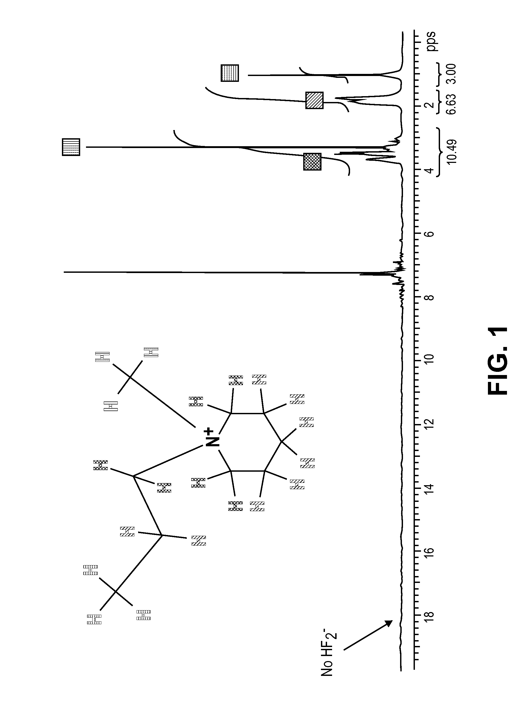
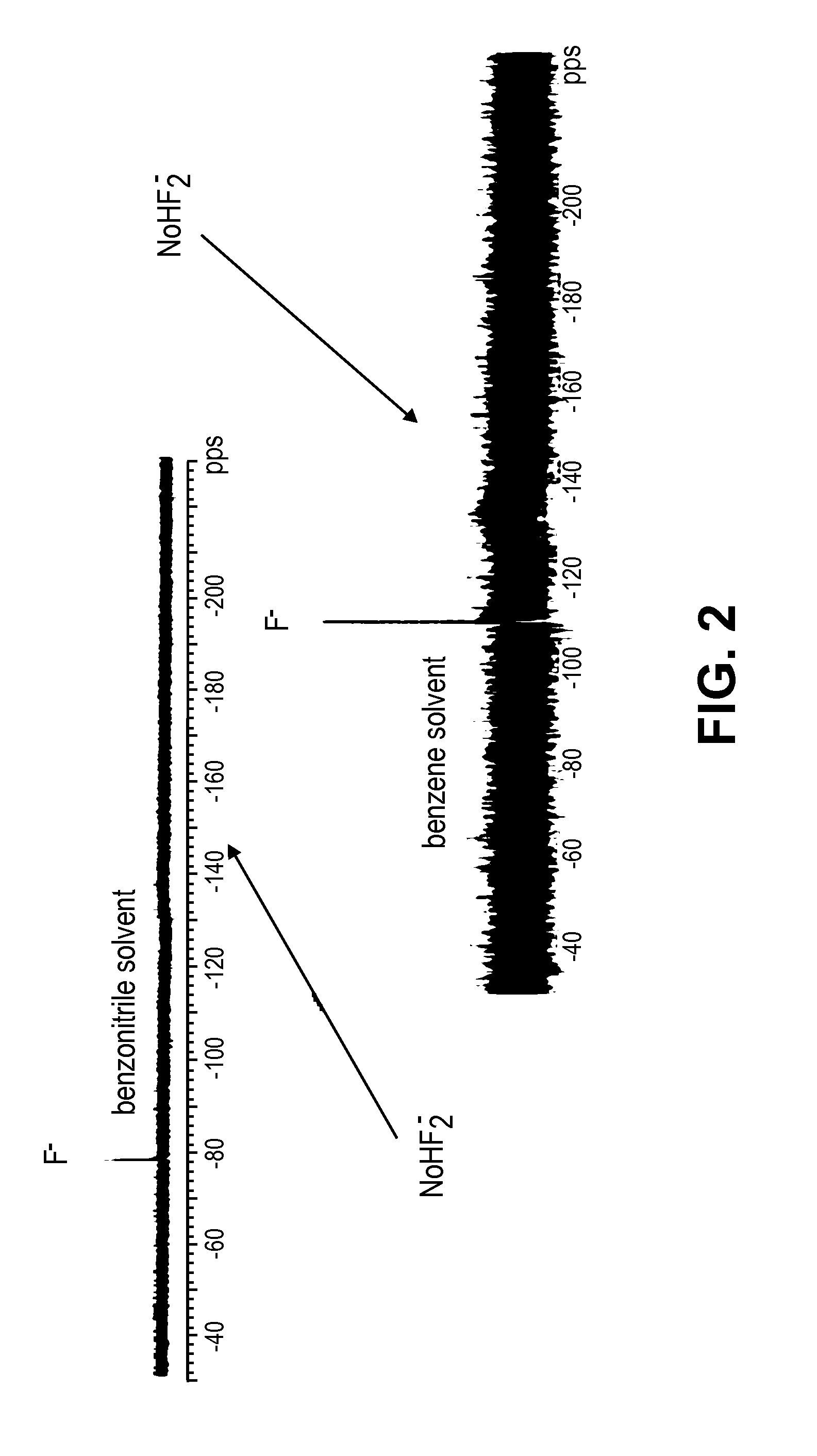
[0064]NMR spectroscopy. 0.05 g MPPF was dissolved in 1 mL dry C6D6 in an Ar-filled glovebox, and investigated by 1H and 19F NMR spectroscopy. FIG. 1 shows the 1H NMR spectrum, indicating the presence of MPP+ cation in stable form. FIG. 2 shows the 19F spectrum, indicating the presence of F− ion in solution, at similar chemical shift to that observed for other “naked” fluoride ions in C6D6 solution described in Schwesinger et al., Chem. Eur. J., 2006, 12, 438. No impurity peaks due to HF or HF2− were observed in this spectrum.

example 3

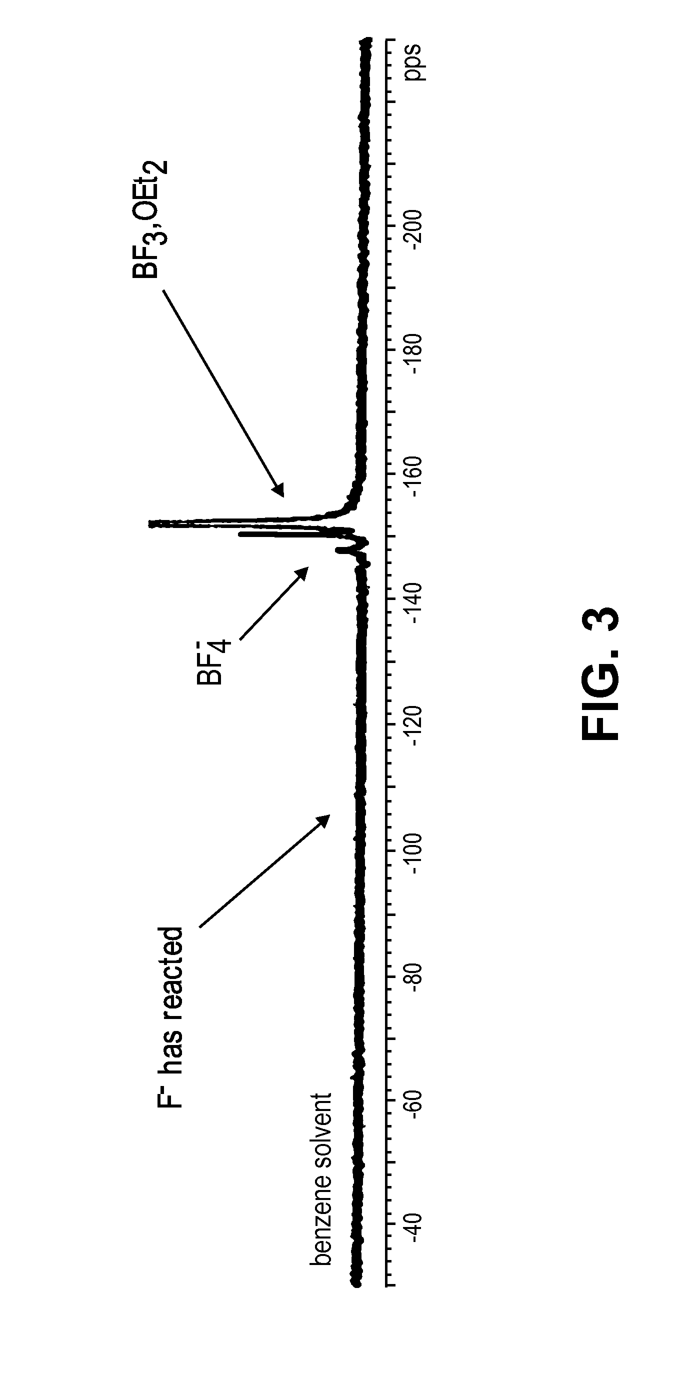
[0065]Reactivity of MPPF in solution. To the solution of MMPF in C6D6 described in Example 2 was added ˜0.1 mL BF3.OEt2 in dry Et2O. 19F NMR spectroscopy shown in FIG. 3 indicated the quantitative consumption of F− to give BF4−, thus demonstrating the reactivity of the F− ion in organic solution.


PUM


Abstract

A fluoride ion battery includes a substantially lithium-free anode and cathode. At least one of the anode or cathode contains fluorine, and a substantially lithium-free liquid electrolyte is used for charge transport. The electrolyte is liquid at temperatures below about 200 degrees Celsius, and can be formed from an organic-soluble fluoride salt dissolved in selected classes of solvents.

Description

RELATED APPLICATION[0001]This application claims the benefit of U.S. Provisional Application No. 61 / 285,903, filed Dec. 11, 2009, the disclosure of which is incorporated by reference herein.FIELD OF THE INVENTION[0002]The present invention relates to non-aqueous electrochemical cells based on fluoride ion transfer, suitable liquid electrolyte compositions containing fluoride ion salts, and to their use in electrochemical cells, including batteries, capacitors, supercapacitors, and galvanic cells.BACKGROUND AND SUMMARY[0003]A battery generally includes a positive electrode (cathode during discharge), a negative electrode (anode during discharge) and an electrolyte for ion transport. The electrolyte can contain one or more ionic species that that act as charge carriers. Many widely available battery systems are based on cation electrode reactions, with electrodes capturing or releasing a cation from an electrolyte and balancing the charge with an electron from the external circuit. Be...

Claims


Application Information

Patent Timeline
IPC IPC(8): H01M10/05H01M10/02
CPCH01M4/5835H01M2300/0045H01M10/399H01M10/0566C07D295/037Y02E60/10H01M4/36H01M10/0525H01M10/0568H01M10/0569
Inventor WEISS, CEDRIC M.JONES, SIMON CHRISTOPHERTIRUVANNAMALAI, ARUNKUMARDAROLLES, ISABELLEALAM, MAKSUDUL M.HOSSAIN, SOHRAB
Owner CALIFORNIA INST OF TECH
Learn More