
Strontium oxyorthosilicate phosphors having improved stability under a radiation load and resistance to atmospheric humidity

a technology of oxyorthosilicate phosphors and stable phosphors, which is applied in the field of inorganic phosphors, can solve the problems of relatively high moisture sensitivity of europium-doped alkaline earth metal oxyorthosilicates and relatively short life of leds produced from such phosphors, and achieve the effect of increasing stability

Active Publication Date: 2011-06-23
SEOUL SEMICONDUCTOR +1
View PDF14 Cites 4 Cited by
  • Summary
  • Abstract
  • Description
  • Claims
  • Application Information

AI Technical Summary

Benefits of technology

[0010]Exemplary embodiments of the present invention provide chemically modified oxyorthosilicate phosphors having increased stability under exposure to atmospheric humidity, which are suitable as efficient radiation converters for use in different technical applications.

Problems solved by technology

However, under specific conditions LEDs produced from such phosphors may have a comparatively short lifetime.
A possible cause of this disadvantageous behavior may be the relatively high moisture sensitivity of the europium-doped alkaline earth metal oxyorthosilicates.

Method used


Image

  • Strontium oxyorthosilicate phosphors having improved stability under a radiation load and resistance to atmospheric humidity
  • Strontium oxyorthosilicate phosphors having improved stability under a radiation load and resistance to atmospheric humidity
  • Strontium oxyorthosilicate phosphors having improved stability under a radiation load and resistance to atmospheric humidity

Examples


working example 1

[0034]For the preparation of a phosphor having a low Ca fraction in the composition Sr2.9285Ca0.03Cu0.0015SiO5:Eu0.04, 432.4 g of SrCO3, 3.0 g of CaCO3, 0.12 g of CuO, 7.04 g of Eu2O and 60.94 g of SiO2 are used as starting materials, to which 1.5 g of NH4F is added as a flux. After thorough homogenization, the batch mixture is transferred to corundum crucibles which are positioned in a high-temperature furnace. There, the solid mixtures are subjected to an is ignition regime which has a first 3 hour holding stage at 1200° C. and a second 5 hour holding stage at 1550° C. The ignitions are effected in pure oxygen until the 1550° C. ramp is reached and in an N2 / H2 mixture that contains 20% of hydrogen during the 1550° C. phase. The post-treatment of the cooled ignited material includes its milling, the carrying out of wash processes, and the drying and screening of the end product.

working example 2

[0035]For the preparation of an alkaline earth metal oxyorthosilicate phosphor of the inventive composition Sr2.91Ca0.04Ba0.01SiO5:Eu0.04, 429.6 g of SrCo3, 1.97 g of BaCo3, 4.01 g of CaCo3, 7.04 g of Eu2O3, 60.9 g of SiO2 and 0.54 g of NH4Cl are thoroughly mixed and then ignited for 6 hours at a temperature of 1380° C. in an N2 / H2 atmosphere having a proportion of 20% of hydrogen. After the end of the ignition process, the ignited material is homogenized by milling and then subjected again to a thermal treatment for two hours at 1350° C. in a reducing N2 / H2 atmosphere having a hydrogen concentration of at least 5%. The final post-treatment of the synthesized phosphor sample is effected in the manner described in Example 1.

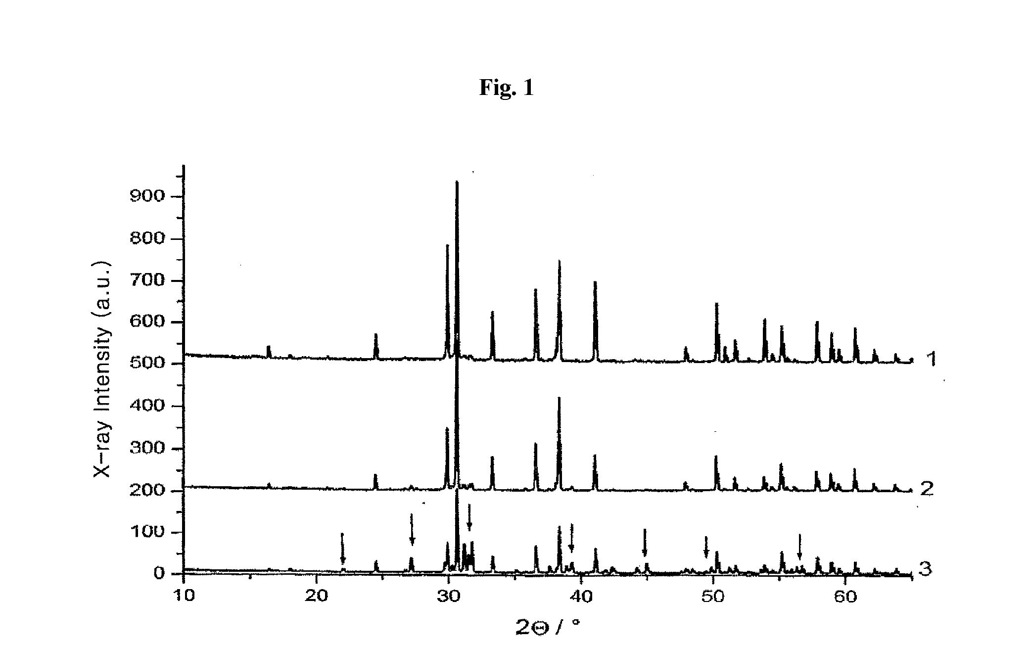
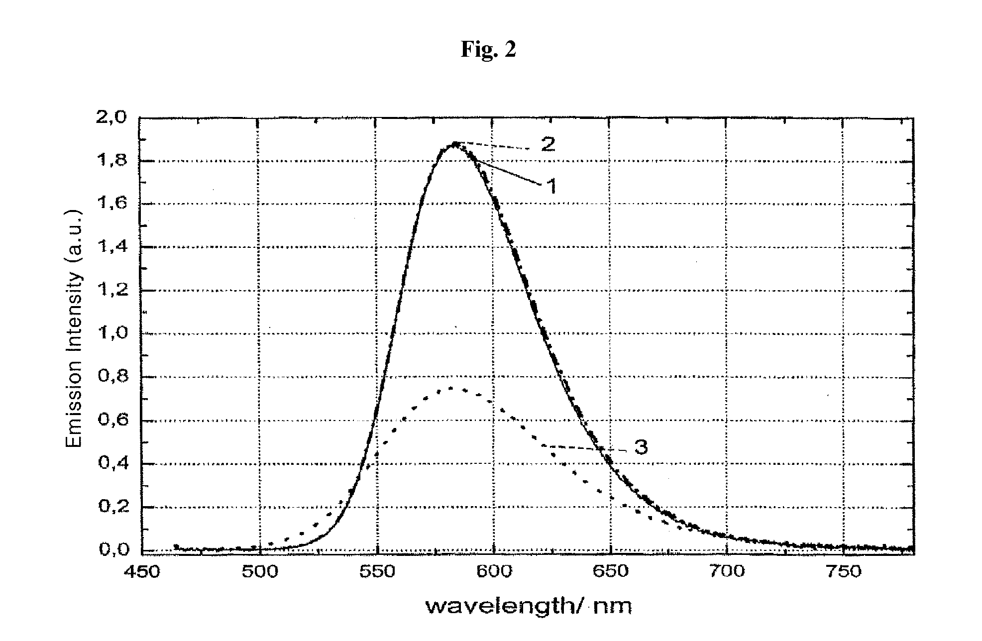
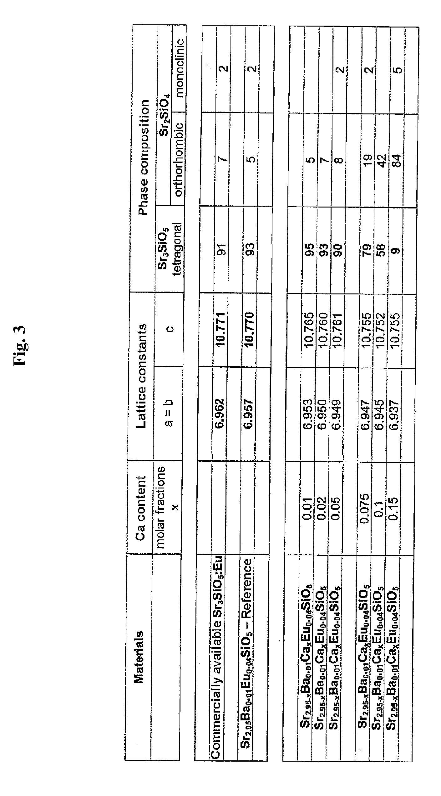
[0036]FIG. 1 shows the X-ray diffraction diagrams of europium-activated strontium oxyorthosilicate phosphors which differ from one another in the proportion of added calcium. Diffraction diagram 1 relates to the comparative material Sr2.95Ba0.01Eu0.04SiO5. Diffrac...


PUM


Abstract

Exemplary embodiments of the present invention relate to inorganic phosphors based on silicate compounds having improved stability under a resulting radiation load and resistance to atmospheric humidity, which are capable of converting higher-energy excitation radiation, i.e. ultraviolet (UV) or blue light, with high efficiency into a longer-wavelength radiation which may be in the visible spectral range. A calcium molar fraction x having a value between 0 and 0.05 is added to a silicate phosphor having the general formula Sr3-x-y-zCaxMIIySiO5:Euz.

Description

CROSS-REFERENCE TO RELATED APPLICATION[0001]This application claims priority from and the benefit of German Patent Application No. 10 2009 059 798.0, filed on Dec. 21, 2009, which is hereby incorporated by reference for all purposes as if fully set forth herein.BACKGROUND OF THE INVENTION[0002]1. Field of the Invention[0003]Exemplary embodiments of the present invention relate to inorganic phosphors based on silicate compounds which convert higher-energy excitation radiation, i.e. ultraviolet (UV) or blue light, with high efficiency into a longer-wavelength radiation which may be in the visible spectral range.[0004]2. Discussion of the Background[0005]Phosphors may be used in light sources such as light emitting diodes (LEDs), which emit colored or white light. In an LED, phosphors, which may be used in combination with other luminophores, are used to convert ultraviolet or blue primary radiation emanating from the LED into a longer wavelength secondary radiation, in particular whit...

Claims


Application Information

Patent Timeline
IPC IPC(8): C09K11/79C09K11/54C09K11/81
CPCH05B33/14C09K11/7734C09K11/77342C09K11/08C09K11/59C09K11/77922
Inventor LEE, CHUNG HOONTEWS, WALTERROTH, GUNDULASTARICK, DETLEF
Owner SEOUL SEMICONDUCTOR
Learn More