Integrated infrared sensors with optical elements, and methods
- Summary
- Abstract
- Description
- Claims
- Application Information
AI Technical Summary
Benefits of technology
Problems solved by technology
Method used
Image
Examples
Embodiment Construction
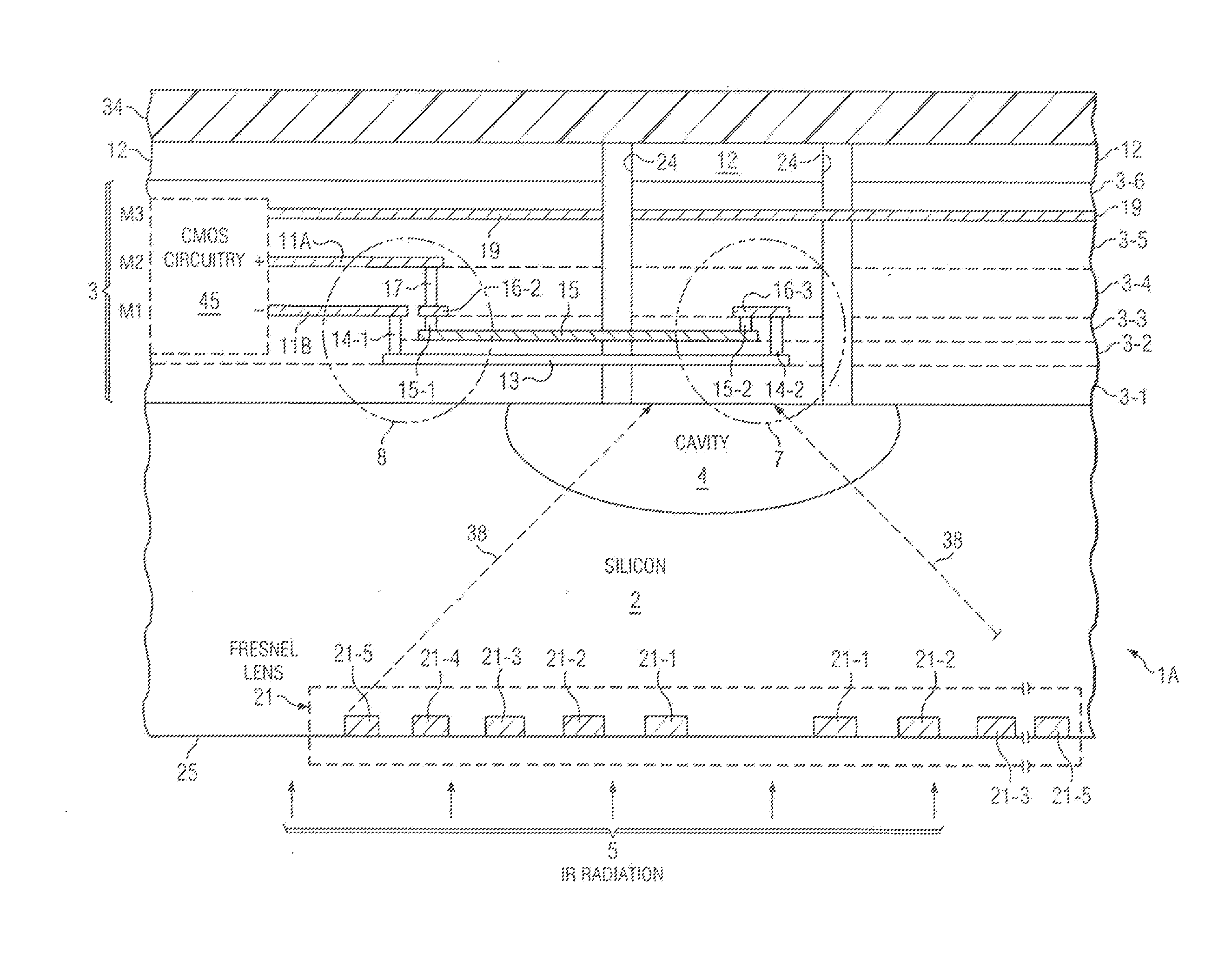
[0064]FIG. 3 shows a detailed cross-section of an integrated circuit IR sensor chip 1A which includes silicon substrate 2 and cavity 4 therein, generally as shown in FIG. 5 except that chip 1 as shown in FIG. 5 is inverted. Silicon substrate 2 includes a thin layer (not shown) of epitaxial silicon into which cavity 4 is etched, and also includes the silicon wafer substrate on which the original epitaxial silicon layer is grown. IR sensor chip 1 includes SiO2 stack 3 formed on the upper surface of silicon substrate 2. SiO2 stack 3 includes multiple oxide layers 3-1, 2 . . . 6 as required to facilitate fabrication within SiO2 stack 3 of N-doped polysilicon layer 13, titanium nitride layer 15, tungsten contact layers 14-1, 14-2, 15-1, 15-2, and 17, first aluminum metallization layer M1, second aluminum metallization layer M2, third aluminum metallization layer M3, and various elements of CMOS circuitry in block 45. (Note however, that in some cases it may be economic and / or practical t...
PUM
 Abstract
Description
Claims
Application Information
 - R&D
- Intellectual Property
- Life Sciences
- Materials
- Tech Scout
- Unparalleled Data Quality
- Higher Quality Content
- 60% Fewer Hallucinations
Browse by: Latest US Patents, China's latest patents, Technical Efficacy Thesaurus, Application Domain, Technology Topic, Popular Technical Reports.
© 2025 PatSnap. All rights reserved.Legal|Privacy policy|Modern Slavery Act Transparency Statement|Sitemap|About US| Contact US: help@patsnap.com


