
Method for forming a blood flow in surgically reconstituted segments of the blood circulatory system and devices for carrying out said method

a blood flow and surgical technique, applied in the field of anatomy, physiology, and pathophysiology of blood circulation, can solve the problems and achieve the effect of reducing the risk of thrombosis and blood injury

Inactive Publication Date: 2011-06-23
BOKERIYA LEO ANTONOVICH +2
View PDF2 Cites 77 Cited by
  • Summary
  • Abstract
  • Description
  • Claims
  • Application Information

AI Technical Summary

Benefits of technology

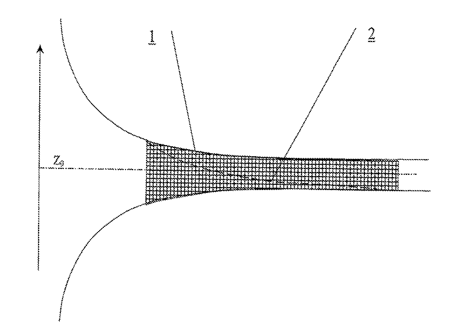
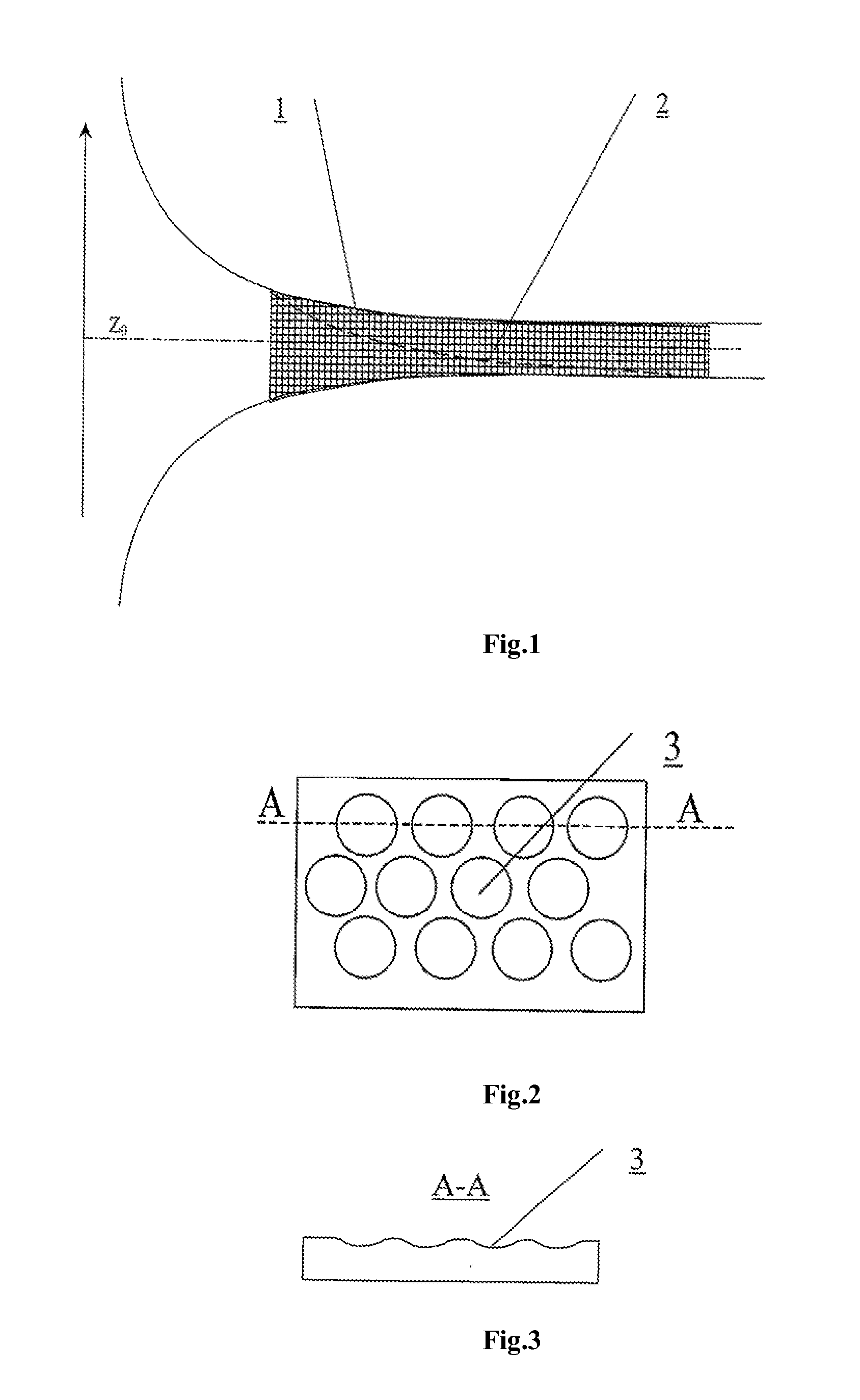
[0050]The technical effect achieved by using the vessel prosthesis of this invention is causing blood to flow inside the prosthesis in a stream identical in structure to a physiological swirled flow that is free from stagnation and separation zones and reducing the risk of thrombosis, blood injury, and hyperplasia in the prosthesis implantation area.
[0054]The technical effect produced by using the cannula of this invention is maintaining a blood flow inside the cannula that is identical in structure to the physiological swirled flow that is free from stagnation and separation zones and reduces the risk of thrombosis, blood injury, and channel hyperplasia in the prosthesis implantation area. Moreover, the blood flow at the inlet and outlet of the cannula is combined (joined) in terms of velocity and pressure values with the blood flow entering the cannula and the blood flow in the vessel downstream of the cannula.
[0058]The cannula may be made of an elastic material of flexibility that helps maintain conformity of the parameters Q(t) and Z0(t) to individual blood circulation norms along the flow channel of the cannula at every moment of the cardiac cycle.
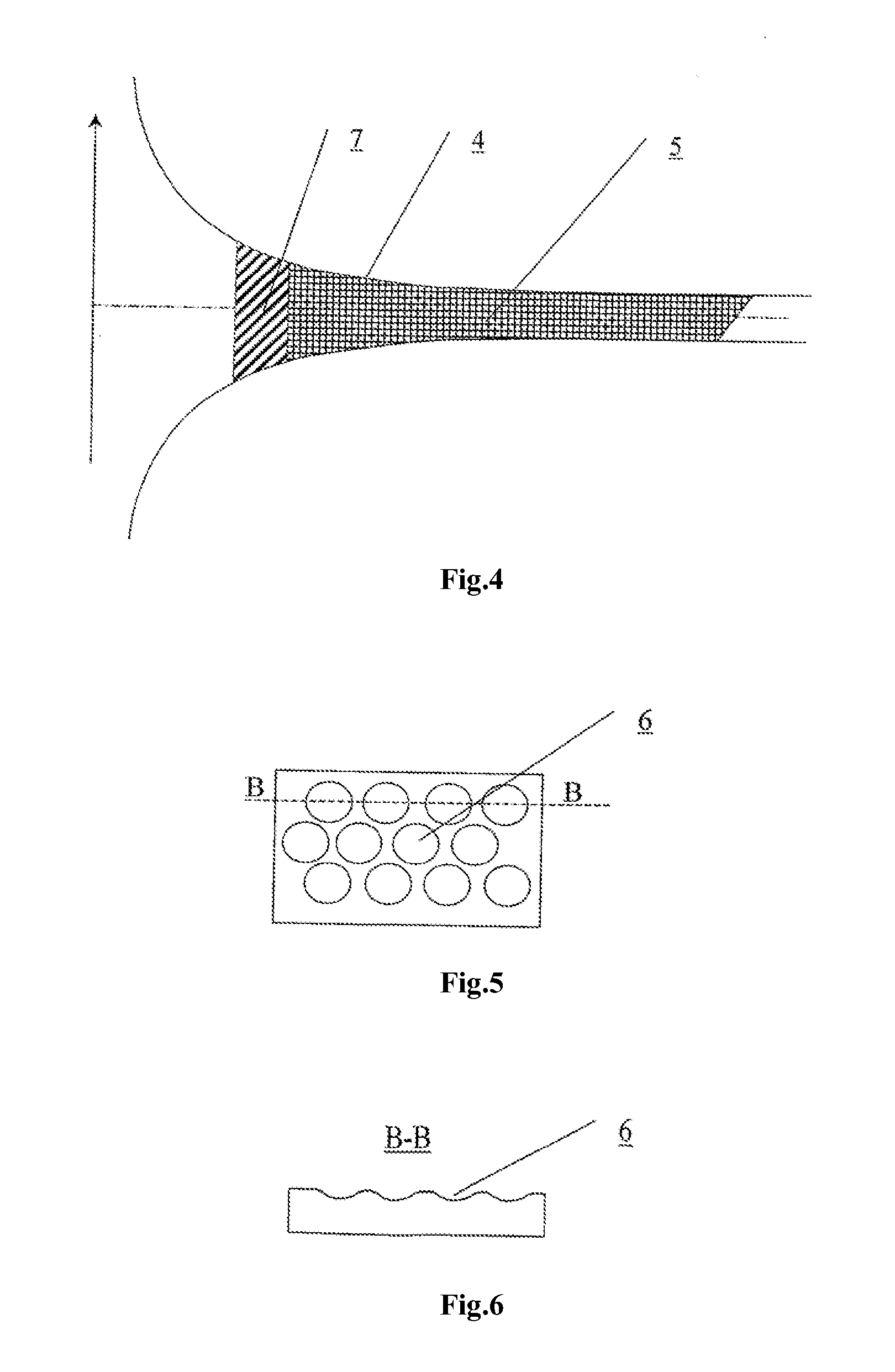
[0059]The technical effect produced by using the heart valve prosthesis of this invention is blood flow through the prosthesis that is identical in structure to the physiological swirled blood flow free from stagnation and separation zones and reducing the risk of thrombosis and blood injury.
[0062]The technical effect produced by the blood pump of this invention is maintaining a swirled flow free from stagnation and separation zones in the pump working chamber and at the outlet thereof so that the risk of thrombosis and blood injury is reduced. The flow formed in the pump is combined (joined) at the pump inlet and outlet, in terms of velocity field and pressure, with the blood flows at the connection points thereof.

Problems solved by technology

These findings led to an assumption that the blood in the central parts of the circulation system flows in the form of a swirled stream, and yet direct visualization and determination of the structure of a real or modeled flow were unsuccessful.
These studies, too, failed to provide a quantified description of the blood flow because of the absence of analytical or numerical methods for modeling current in a channel of complex geometric configuration such as a blood stream.
In the absence of an adequate hydrodynamic model of swirled flow, designers of these products could not use quantified ratios associating blood flow characteristics with the geometry of the flow channel of the streams formed.
Besides, these assumptions disregarded the structural specifics and the non-stationary nature of the swirled blood flow.
As a result, the flow modeled on the basis of these assumptions could not restore the normal hydrodynamic characteristics of the blood circulation system without producing stagnation zones and flow separation zones that are factors provoking thrombosis, blood injury, and hyperplasia in the blood stream.
The proposals described below as prior art could not, therefore, be used as functionally complete organ-substituting devices for the cardiovascular system.
The prior art method, however, does not create conditions in which a flow swirled around the axis of a curved channel develops and maintains rotation around its own axis of symmetry.
The method disregards the considerable losses of flow energy as the flow interacts with the wall, nor does it have the conditions to prevent formation of stagnation zones.
All parameters of flow swirling are of a speculative, qualitative nature, and are not supported experimentally.
Apart from the above, the prior art method has the following drawbacks:absence of conditions for the parameters of the swirled blood flow and cannula design (radius, curvature and pitch of flow swirling, and so on) to conform to the patient's individual blood circulation norms;absence of desired boundary conditions of the swirled flow in the cannula to define conditions for interaction between the blood flow and the walls of the flow channel;absence of desired initial conditions needed to form a swirled flow in the coil, which conditions determine the velocity field in the flow, its space and time characteristics, the shape of the flow channel, and direction of flow;disregard for the non-stationary nature of the flow such as changes in the flow velocity components over the cardiac cycle; andrestriction of the possible types of cannulas to a single design of the prior art invention.
This prior art prosthesis is disadvantageous because it cannot produce a blood flow having desired characteristics corresponding to the patient's individual norms.
The prior art device is disadvantageous because it does not provide conditions for joining the flow upstream of the valve, at the valve, and downstream of the valve.
This inconsistency leads to further energy losses and flow disturbance at the valve, increasing the risk of thrombosis and blood injury and lowering the functional characteristics of the device.
This device is disadvantageous because it lacks conditions for joining currents upstream and downstream of the pump, for which reason it cannot prevent formation of stagnation zones and flow separation zones and, therefore, it increases the risk of thrombosis and blood injury in the through-flow chamber of the pump.
This device is disadvantageous because it cannot be used to form a flow of blood or model fluid having desired swirling characteristics.

Method used


Image

  • Method for forming a blood flow in surgically reconstituted segments of the blood circulatory system and devices for carrying out said method
  • Method for forming a blood flow in surgically reconstituted segments of the blood circulatory system and devices for carrying out said method
  • Method for forming a blood flow in surgically reconstituted segments of the blood circulatory system and devices for carrying out said method

Examples


Embodiment Construction

[0092]It has been demonstrated by morphological, functional, and experimental methods that the pulsating blood flow in the heart and great vessels has a swirled structure that allows blood to be transported without energy losses and formation of flow separation and stagnation zones.

[0093]A quantitative analysis of the structure of a blood flow being formed, and the mechanisms for generating it and its evolution in the heart and great vessels undertaken by exact solutions of non-stationary hydrodynamic flows of a viscous fluid (Kiknadze G. I., Krasnov Yu. K., Evolution of a Spout-Like Flow of a Viscous Fluid, Sov. Phys. Dokl. 1986; 31(10): 799-801), helped, on the basis of experimental and clinical studies, to prove consistency of the resultant exact solutions with the well-known patterns of blood circulation physiology. As a result, a conception was formulated to match the specificities of swirled blood flow and blood circulation function (Kiknadze G. I., Oleinikov V. G., Gachechila...


PUM


Abstract

The invention relates to clinical cardiology and cardiovascular surgery. The method for forming a blood flow in research stands and in surgically reconstructed segments of the blood circulation system comprises diagnosing the individual condition of a patient's blood circulation system; measuring the blood flow velocity field in the heart chambers and great vessels; comparing the parameters measured against the physiological norm; determining parameters forming a swirled blood flow; and modeling an individual swirled blood current in the blood circulation system being diagnosed, the streamlined surfaces and guide elements of flow channels of the blood circulation system reconstructed being given shapes conforming to the flow lines of the restored normally swirled blood flow in accordance with formulas:Q(t)=[z+Z0(t)]2(1.1)ϕ=ϕ0+k(t)z(1.2)k(t)=Γ0(t) / 4πQ(t)C0(t)Vz=2C0(t)zVr=-C0(t)rVϕ=Γ0(t)2πr{1-exp[-C0(t)r22v]}(1.3)wherein: Vr, Vz, and Vφ are the radial, longitudinal, and tangential velocities of the swirled current; v is the kinematic viscosity of the medium; φ0 is the initial swirling angle in relation to the flow axis normal; φ, z and r are current values of the angular, longitudinal, and radial coordinates along the flow line; and Q(t), Z0(t), k(t), Γ0(t), and C0(t) are parameters of the swirled blood flow variable over time because of the non-stationary current and corresponding to the individual normal indicators for a physiologically swirled blood flow. The normal indicators are established by routine examination of a representative sample of patients having no changes in the cardiovascular system. A vessel prosthesis comprises a tube having an internal surface in contact with the blood flow provided with a pattern to swirl the blood flow in accordance with formulas (1.1 to 1.3) conforming to a specific localization of the segment being reconstructed. A cannula for para-corporeal perfusion devices comprises a flow channel having an internal surface that is provided with a longitudinal pattern to swirl the blood flow, the shape of the pattern being determined from formulas (1.1 to 1.3), relative to the specific localization of the point where the cannula is inserted into the vessel channel. A heart valve prosthesis comprises one or more shutoff elements arranged symmetrically in the center of a body of round and / or oval cross-section, the streamlined surfaces of the valve being provided with a pattern in accordance with formulas (1.1 to 1.3). A blood pump comprises a flow swirling unit, a flow channel, and valves at the inlet and outlet of the channel, the surface washed over by blood being provided with a relief variable over time in accordance with formulas (1.1 to 1.3). A swirling device comprises an end piece having a streamlined surface provided with guides in the form of ribs, grooves, or blades of a shape defined by formulas (1.1 to 1.3), the swirling angle of the guides relative to the flow axis being varied optionally an operator or by a special-purpose device for modeling different current conditions.

Description

FIELD OF THE INVENTION[0001]The invention relates to anatomy, physiology, and pathophysiology of blood circulation, clinical cardiology, and cardiovascular surgery.[0002]The invention can be used for:[0003]diagnosing blood circulation conditions and planning the tactics and scale of surgery in operations on the heart and vessels according to the criterion of restoration and maintenance of a physiological swirling structure of the blood flow;[0004]designing organ-substituting implants used in cardiovascular surgery, including cardiac valve prostheses, blood vessel prostheses, a fully implanted artificial heart, and so on, which form and maintain a blood flow of a physiological swirling structure;[0005]designing pumps, arteries, and cannulas used in assist and artificial blood circulation systems that form and maintain a required swirling blood flow structure; and[0006]modeling blood circulation physically for research and testing purposes allowing a flow of a model fluid or blood of ...

Claims


Application Information

Patent Timeline
IPC IPC(8): A61M1/10A61F2/82A61F2/24A61F2/06
CPCA61B5/026A61B5/055A61B8/06A61F2/2412A61F2002/068A61F2240/001A61M1/122A61M1/101A61M2206/16G06F19/3437G06T17/00G06T2210/41A61F2250/0039A61M2205/3334G16H50/50A61M60/894A61M60/148A61M60/178A61M60/196A61M60/523
Inventor BOKERIYA, LEO ANTONOVICHGORODKOV, ALEXANDR YURIEVICHKIKNADZE, GENNADY IRAKLIEVICH
Owner BOKERIYA LEO ANTONOVICH
Learn More