Separation of particles in liquids by use of a standing ultrasonic wave

a standing ultrasonic wave and particle technology, applied in separation processes, laboratories, instruments, etc., can solve the problems of unsuitable milk sample microscopy, inability to detect particles in samples, and inability to transmit infrared spectroscopy transmission losses, etc., to reduce the amount of reagents, reduce the requirement of reagents, and reduce the sensitivity.

Inactive Publication Date: 2011-06-30
FOSS ANALYTICAL AS
View PDF8 Cites 113 Cited by
  • Summary
  • Abstract
  • Description
  • Claims
  • Application Information

AI Technical Summary

Benefits of technology

[0009]The present invention is intended to reduce the sensitivity towards the presence of fat globules and other low density particles and to reduce the requirements for reagents in particle detection and counting devices, by employing the known technique of acoustophoresis in a novel and inventive way. The novel principle is based on the use of a sheath liquid separating a liquid containing particle from the walls of the flow channel in combination with a particular order of the standing wave pattern and a particular ratio of the sheath liquid to sample liquid flow rates. In this way the drawbacks of particles blocking or disturbing the flow, is removed or significantly reduced, which will contribute to reducing the amount of reagents added in technologies for counting biological cells.

Problems solved by technology

When analysing liquid food products, the presence of particles in the sample after filtering may pose particular problems.
E.g. the largest fat particles in milk lead to significant light scattering, which makes microscopy unsuited for milk samples and gives rise to transmission losses in infrared spectroscopy of milk.
The addition of such chemicals is in principle unwanted.
It adds to the cost and complexity of the analysis and working with some of the added substances may pose a health threat.
However, the fat globules at the wall will tend to stick to the wall and coalesce, eventually at the risk of blocking or disturbing the flow.

Method used


Image

  • Separation of particles in liquids by use of a standing ultrasonic wave
  • Separation of particles in liquids by use of a standing ultrasonic wave
  • Separation of particles in liquids by use of a standing ultrasonic wave

Examples


Embodiment Construction

[0034]In following a number of embodiments will be presented, with their respective benefits in relation to the subclaims.

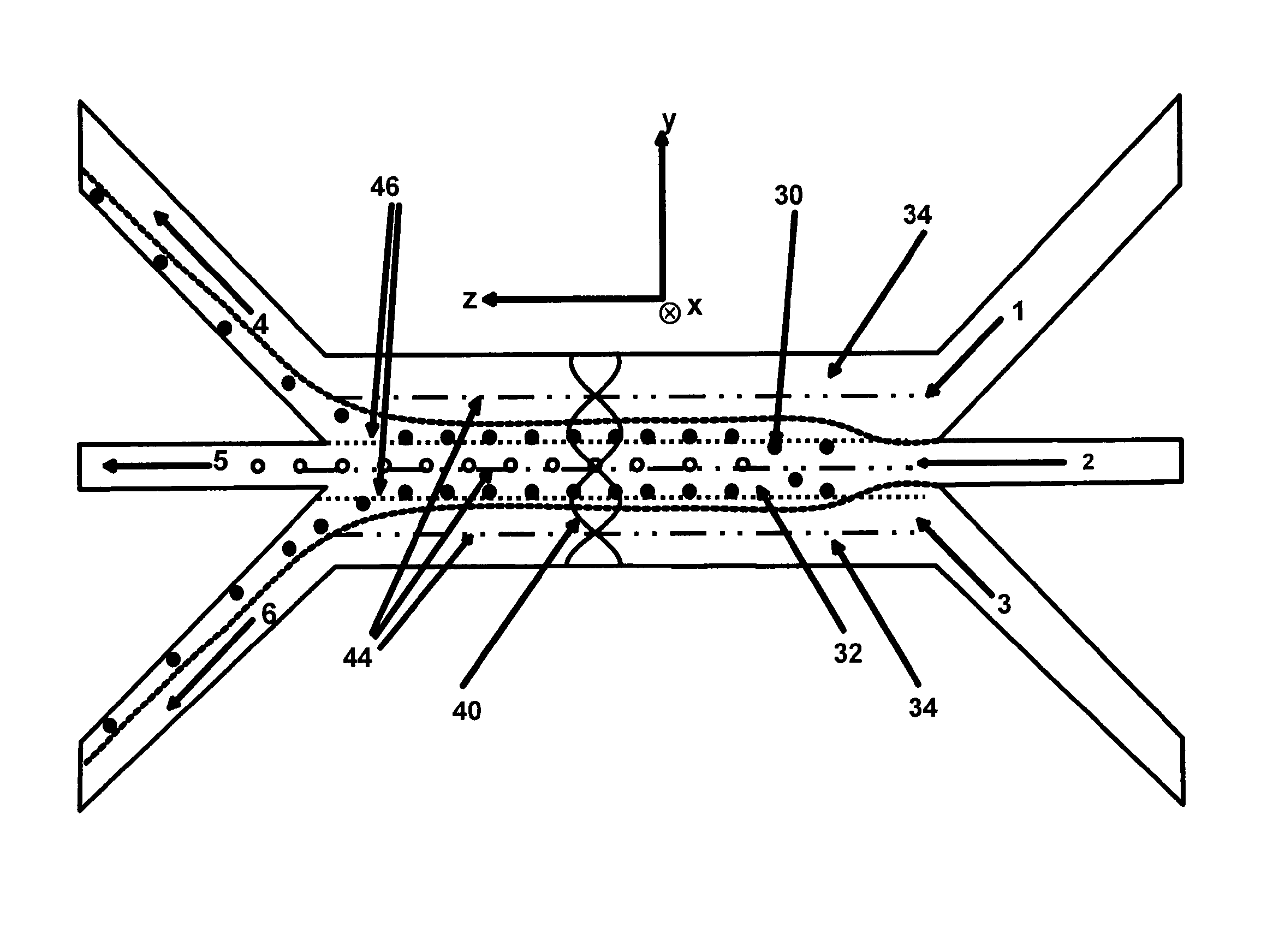
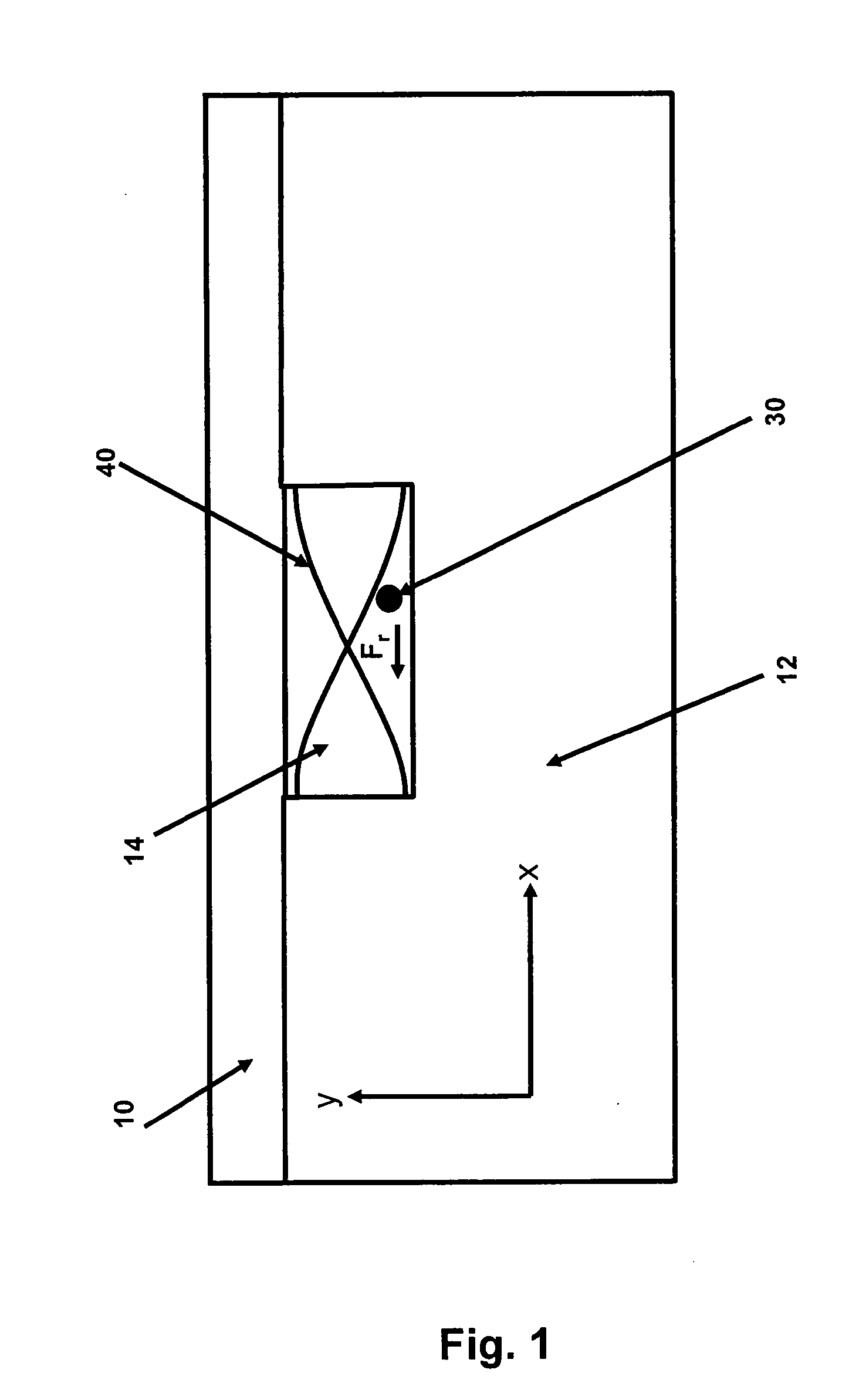
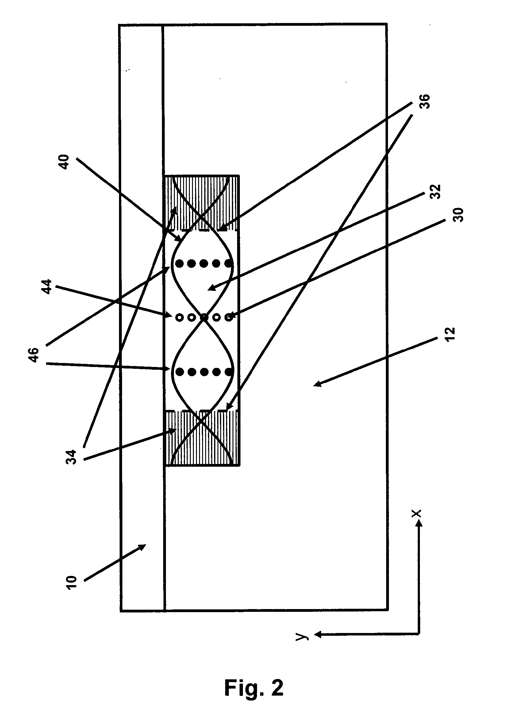
[0035]In a first embodiment of the invention a flow of sample liquid, such as milk, is separated from a compartment wall by a flow of sheath liquid. The sample liquid will contain two types of particles; low density particles such as fat globules and high density particles such as somatic cells. The compartment is connected to a source of ultrasound in a way causing a transfer of ultrasound to the liquid, such as on the side or on the top of the compartment and the size and shape of the compartment must support to a fundamental or higher order ultrasonic standing wave with a channel width corresponding to a whole multitude of λ / 2, i.e. it must have a width of approximately n·λ / 2 (n=1, 2, 3 . . . ) and a height less than λ / 2. In this case the fat globules in the milk will be driven towards the anti-node planes and the cells in the milk towards the node planes. Thi...


PUM

PropertyMeasurementUnit
frequencyaaaaaaaaaa
frequenciesaaaaaaaaaa
flow rateaaaaaaaaaa

Abstract

The invention relates to a device for manipulation of particles (30) in a sample liquid (32) said device comprising a source of ultrasound (16) capable of emitting ultrasound with a given wavelength, an inlet for a sample liquid (2), one or more outlets (4, 5, 6) and a compartment (14), being dimensioned to support a standing ultrasonic wave (40) of said wavelength, characterised in that the device further comprises an inlet for sheath liquid (1, 3) configured to direct a sheath liquid (34) to extend substantially in parallel to an anti-node plane (46) of the ultrasonic standing wave (40) proximate to a sheathed compartment wall. Specifically the device may be used in combination with a particle enumeration device for enumeration of somatic cells in milk.

Description

TECHNICAL FIELD OF THE INVENTION[0001]The current invention relates to the manipulation, sorting and detection of particles in a sample liquid, such as somatic cells in milk.[0002]In the production of food it is essential to analyse the food contents all the way from the raw materials to the finished products. This is required to monitor and optimize the production, and to ensure the quality of the raw materials as well as the finished products.[0003]When analysing liquid food products, the presence of particles in the sample after filtering may pose particular problems. E.g. the largest fat particles in milk lead to significant light scattering, which makes microscopy unsuited for milk samples and gives rise to transmission losses in infrared spectroscopy of milk. In this case, a simple way of removing the fat particles could facilitate new methods of analysis, higher efficiency of spectroscopic techniques or measurements of components otherwise masked by the presence of fat partic...

Claims


Application Information

Patent Timeline
Patent Type & Authority Applications(United States)
IPC IPC(8): G01N29/02
CPCB01L2300/0816G01N15/1459B01D21/283B01L3/502761G01N33/06B01L2300/0877G01N15/12B01D21/34C12M47/06
Inventor HOLM, CLAUSFOLKENBERG, JACOB RIISGRENVALL, CARL JOHANLAURELL, LARS THOMASAUGUSTSSON, PER
Owner FOSS ANALYTICAL AS
Why Eureka
Try Eureka