Method and apparatus for filtering locking

a filtering lock and filtering technology, applied in multiplex communication, multiplex system, time-division optical multiplex system, etc., can solve the problems of cost and circuit complexity, increase the cost of dithering, and achieve accurate extraction, reduce the area of the circuit board and control circuit, and improve the effect of dithering efficiency

Inactive Publication Date: 2011-06-30
HUAWEI TECH CO LTD
View PDF5 Cites 10 Cited by
  • Summary
  • Abstract
  • Description
  • Claims
  • Application Information

AI Technical Summary

Benefits of technology

[0020]The present invention employ a centralized wavelength locking method of injecting a single dither to a PID / PIC, thereby reducing circuit board area and control circuit complexity; a weak dither signal can be accurately extracted by means of a combination of analog filtering and digital filtering; when the frequency of the dither signal changes, a digital filter only needs to adjust a corresponding parameter to complete the extraction of the dither signal, which achieves high portability and upgradeability. As for a cascade of multiple PIC / PID chips with multi-wavelength modules, the method may be employed with a shared apparatus for filtering locking to perform the wavelength locking on two or more optical waves by means of time division multiplexing.

Problems solved by technology

During the implementation of adding the dither, the inventors found that, since one unique dither signal is added to each wave, hardware and software resources need to be multiplied as the wave number increases, thus incurring the problem of costs and circuit complexity.
Furthermore, since the responsivity of the wave locking device is small, the obtained dither signal is weak; therefore it is difficult to extract an effective dither signal when the microprocessor at the back end performs frequency-domain FFT transform after directly entering the A / D converter for sampling, and with the increase of the wave number, this disadvantage becomes more obvious.
Furthermore, for the application of the PID and PIC with multiple laser device arrays, such a wavelength locking method leads to a complex control circuit and an oversize circuit board, which is against the original aim of saving the size, cost and power consumption by using the PID and PIC.

Method used


Image

  • Method and apparatus for filtering locking
  • Method and apparatus for filtering locking
  • Method and apparatus for filtering locking

Examples


Embodiment Construction

[0026]To solve the problem in the prior art that the cost and circuit complexity are increased and it is difficult to extract an effective dither signal since one unique dither signal is added to each wave, an embodiment of the present invention provides a method for filtering locking.

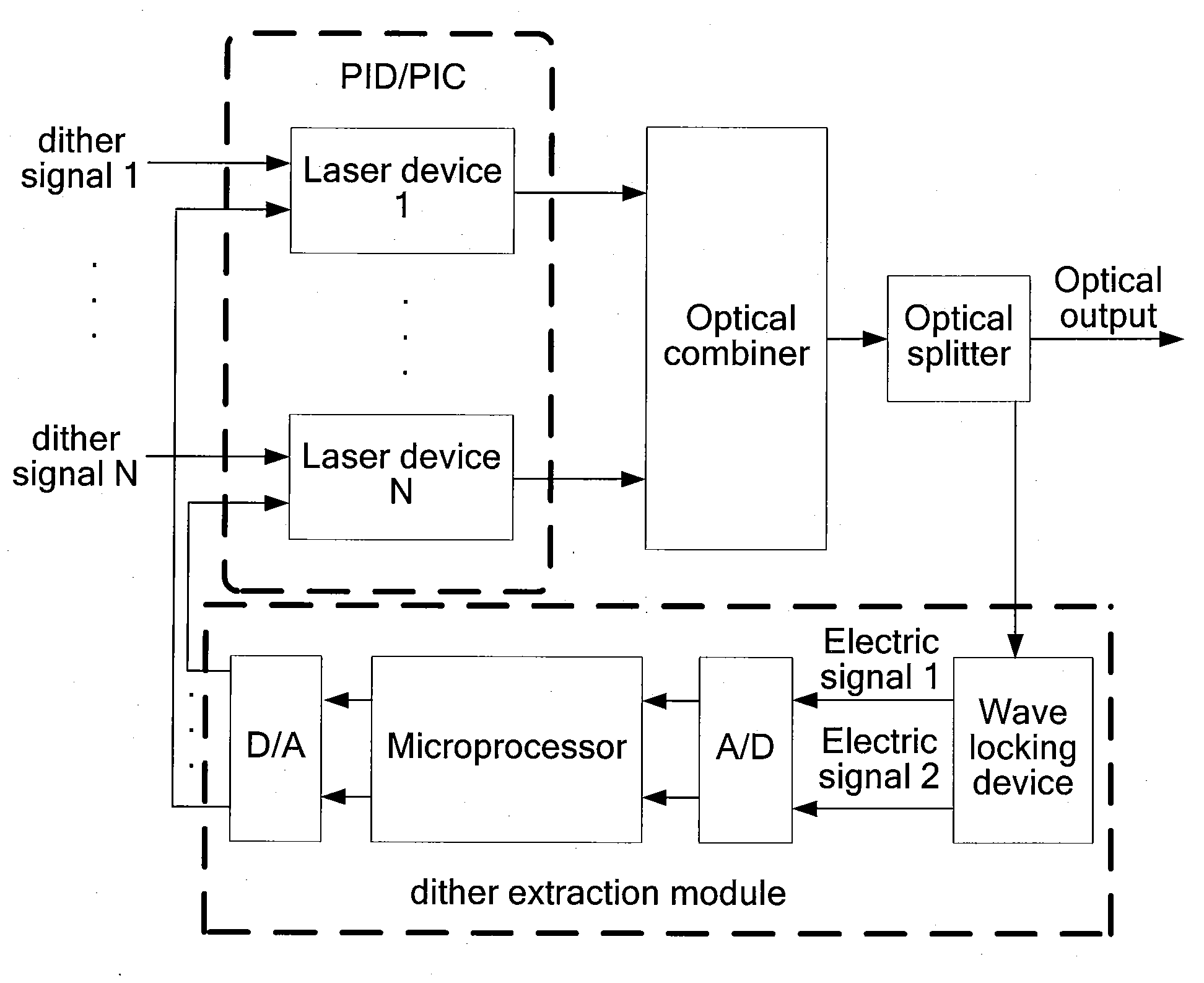
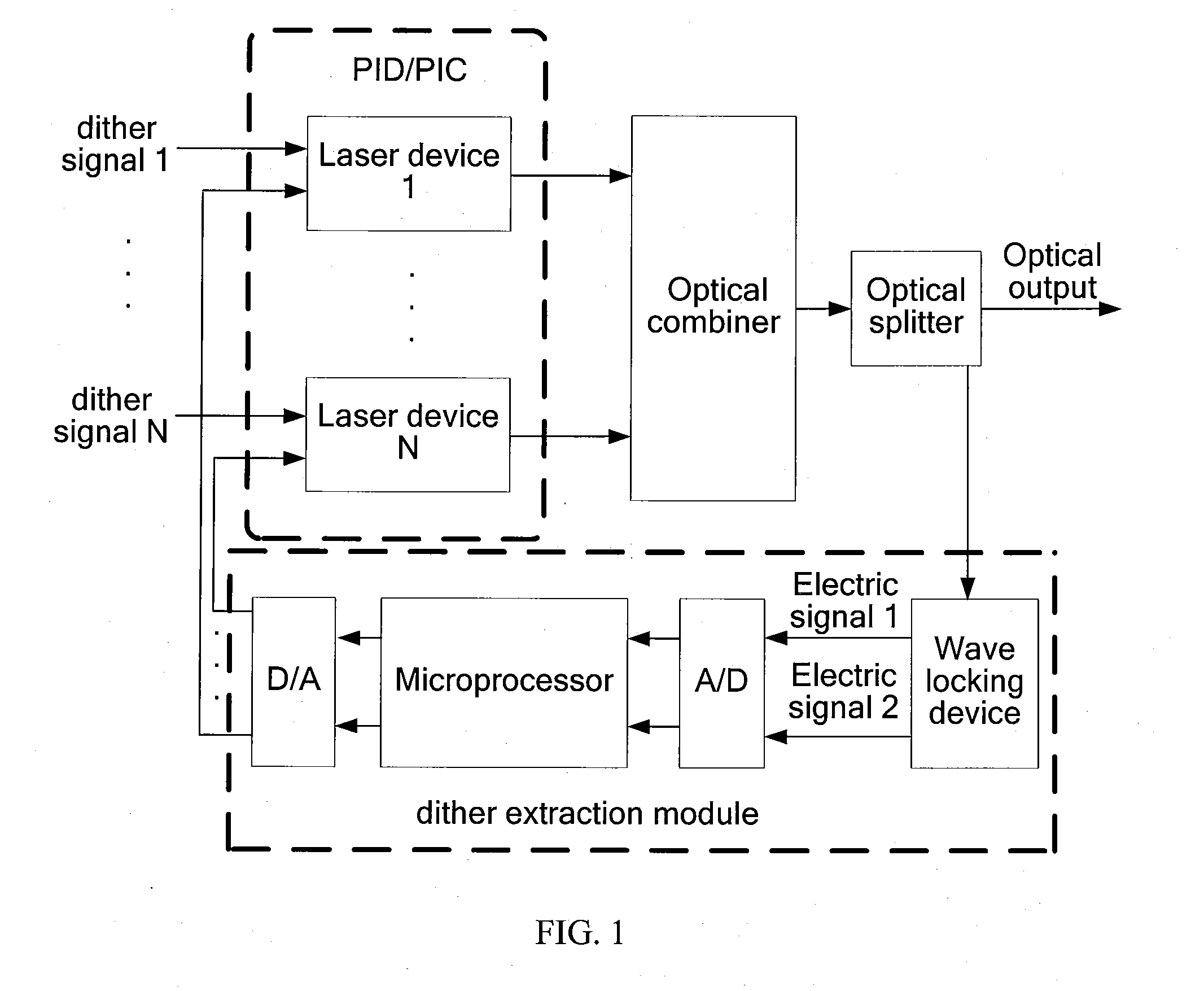
[0027]In a PID / PIC, two or more laser devices exist; each laser device emits a laser; the wavelengths of optical waves emitted by different laser devices are different; the two or more laser devices emit two or more optical waves of different wavelengths, and an optical combiner combines the two or more optical waves into one beam of light and sends the beam.

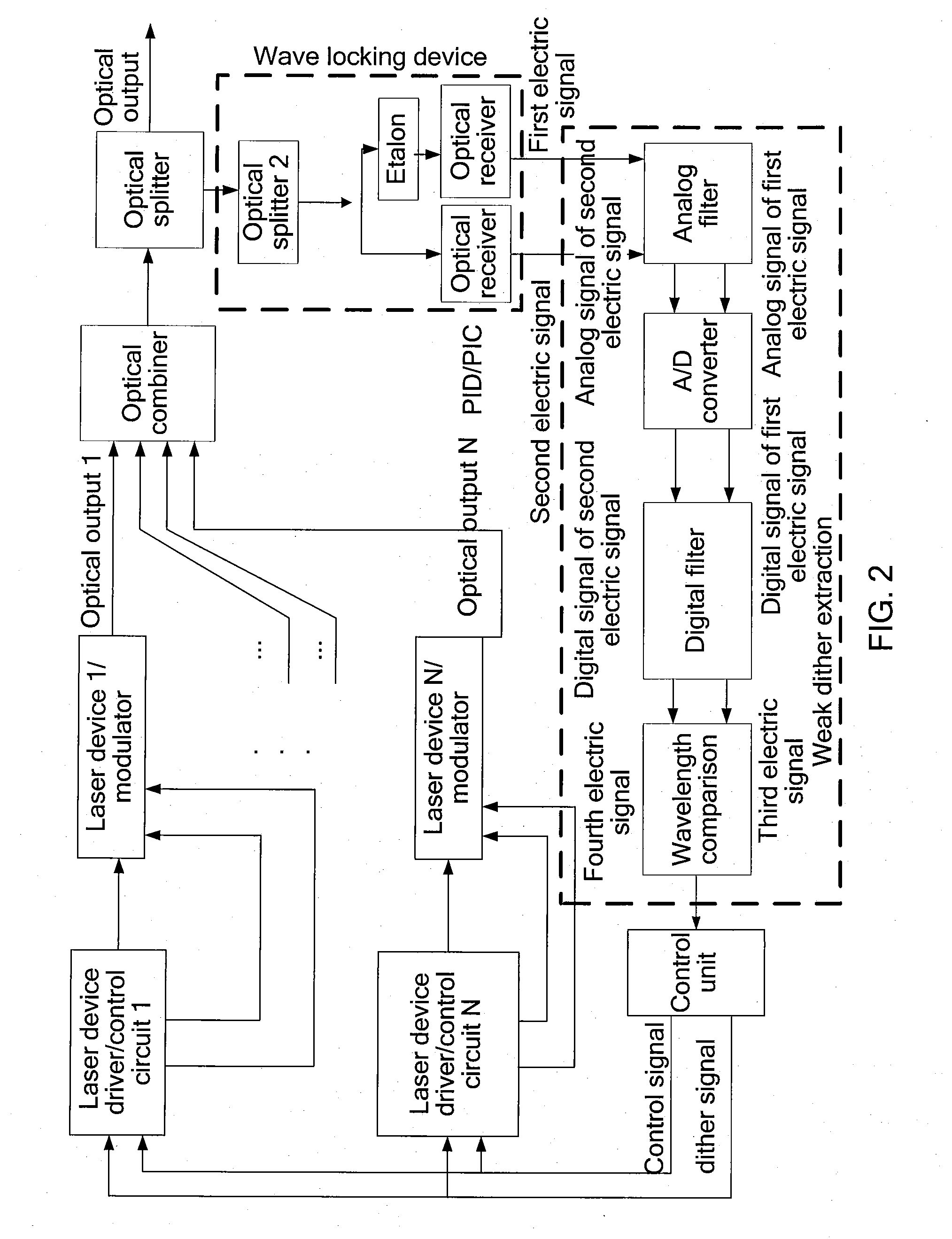
[0028]FIG. 2 is a block diagram of a system for locking two or more wavelengths according to an embodiment of the present invention. Referring to FIG. 2, a control unit includes a dither signal generating apparatus for generating a dither signal and sending the dither signal to a laser device in two or more laser device driver / control circuits at t...


PUM


Abstract

In the field of photonic integrated communication, a method and an apparatus for filtering locking are provided, so as to solve the problem in the conventional wavelength locking technology that any increase of the wave number also incurs increases in costs and circuit complexity, and it is difficult to extract dithered information. The method and apparatus for filtering locking employ a centralized wavelength locking method of injecting a single dither to a Photonic Integrated Device (PID)/Photonic Integrated Circuit (PIC), thereby reducing circuit board area and control circuit complexity. A weak dither signal can be accurately extracted by means of a combination of analog filtering and digital filtering. The technical solution is appropriate for use in photonic integrated systems in which two or more PID/PIC chips with multi-wavelength modules are cascaded.

Description

CROSS-REFERENCE TO RELATED APPLICATIONS[0001]This application is a continuation of International Application No. PCT / CN2009 / 073691, filed on Sep. 2, 2009, which claims priority to Chinese Patent Application No. 200810211900.5, filed on Sep. 9, 2008, both of which are hereby incorporated by reference in their entireties.FIELD OF THE INVENTION[0002]The present invention relates to the field of photonic integrated communication, and in particular, to a method and an apparatus for filtering locking in a Photonic Integrated Device (PID) / Photonic Integrated Circuit (PIC).BACKGROUND OF THE INVENTION[0003]With the development of optical communication services, the integration density of optical devices becomes increasingly higher. For example, as shown in FIG. 1, a PID / PIC includes a laser device array. The laser device array integrates at least two laser devices.[0004]The PID / PIC is connected with an optical combiner. The optical combiner receives lasers emitted by all the laser devices, a...

Claims


Application Information

Patent Timeline
Patent Type & Authority Applications(United States)
IPC IPC(8): H04J14/08H04B10/50H04B10/572
CPCH01S5/06213H01S5/0687H04B10/572H04B10/506H01S5/4087
Inventor TANG, FEIWU, SHUANGQIZHANG, HONGPING
Owner HUAWEI TECH CO LTD
Why Eureka
Try Eureka