Electrokinetic actuator to titrate fluid flow

a technology of electrokinetic actuators and fluid flow, which is applied in the direction of electrodes, diaphragms, wound drains, etc., can solve the problems of coma and/or death, increase in intracranial pressure, and failure to keep up with csf absorption rate production ra

Inactive Publication Date: 2011-06-30
CODMAN NEURO SCI
View PDF11 Cites 28 Cited by
  • Summary
  • Abstract
  • Description
  • Claims
  • Application Information

AI Technical Summary

Benefits of technology

[0018]Yet another aspect of the present invention is directed to the particular use of the previously described electrokinetic actuator in an implantable shunt system for finely titrating cerebrospinal fluid from a proximal catheter to a drainage catheter by controlling an opening pressure and / or diameter of a valve apparatus disposed between the proximal or drainage catheters, wherein fine titration includes full fluid flow and / or complete cut off of fluid flow.

Problems solved by technology

In a patient suffering from hydrocephalus, the CSF absorption rate fails to keep up with the production rate, either because of an obstruction along the natural CSF pathway or due to diseased choroid plexus which increases CSF formation.
The unabsorbed or excess CSF accumulates in the ventricles of the patient's brain, leading to an increase in intracranial pressure.
If left untreated, the increased intracranial pressure can lead to serious medical conditions such as compression of the brain tissue and impaired blood flow to the brain, with such potential consequences as coma and / or death.
This shunt configuration is disadvantageous in that it is limited in the range of resistances offered by the number of different lumens provided.
Furthermore, as acknowledged in the publication itself, the resistors are prone to being clogged with particulate matter such as blood cells.
Such a mixing of the electrolyte with the CSF is impermissible in an implantable shunt system since the mixed fluid (electrolyte and CSF) would be drained into another location within the body; and introducing such an electrolyte into the body would be detrimental from a biological perspective.
Even if such mixing was acceptable, the present inventive system is implanted and thus does not offer ease of access to recharge the pump with new electrolyte to replace the amount that has drained due to operation.
Pressures beyond this maximum range may be lethal or at the very least detrimentally affect the patient.

Method used


Image

  • Electrokinetic actuator to titrate fluid flow
  • Electrokinetic actuator to titrate fluid flow
  • Electrokinetic actuator to titrate fluid flow

Examples


Embodiment Construction

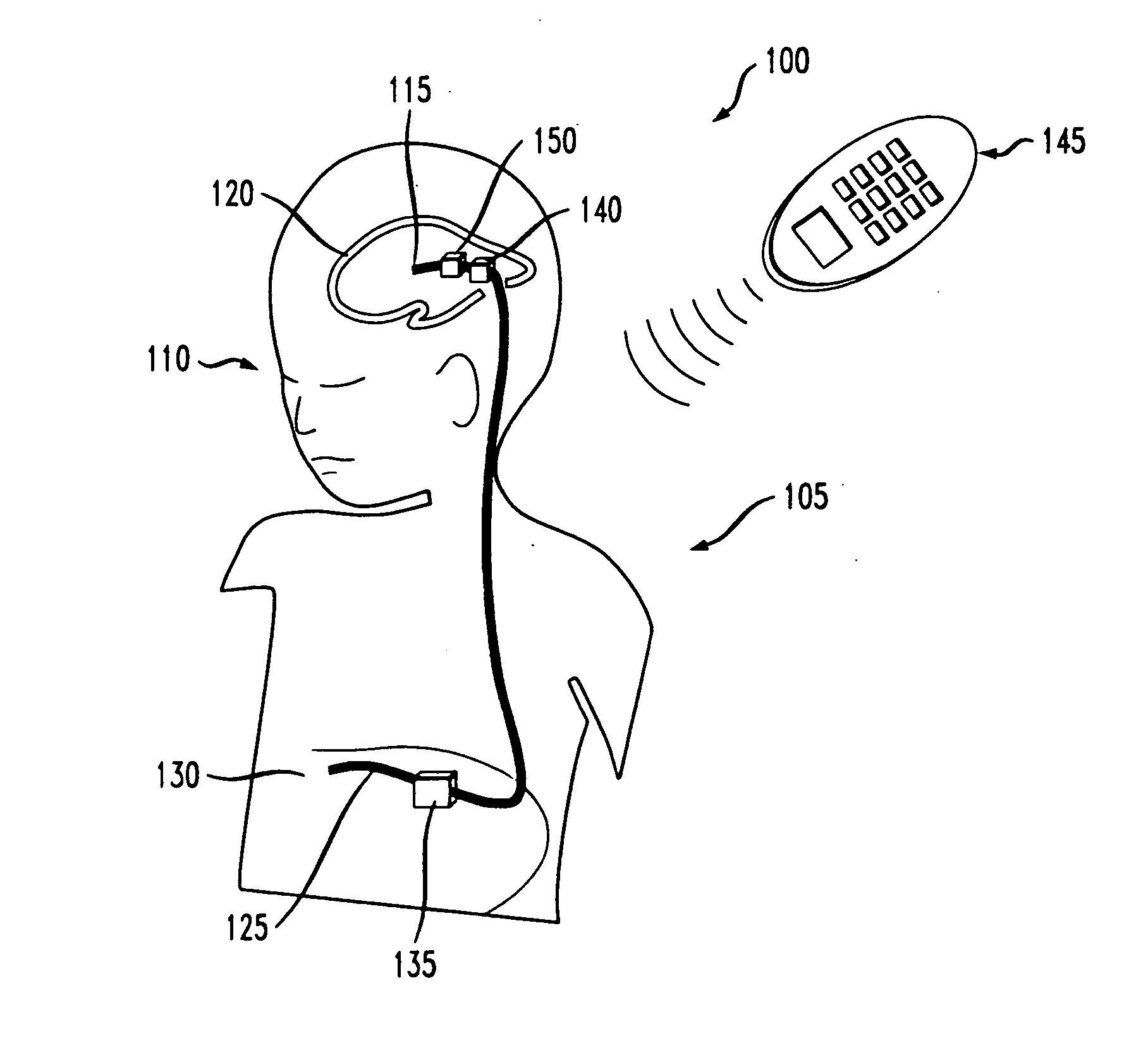
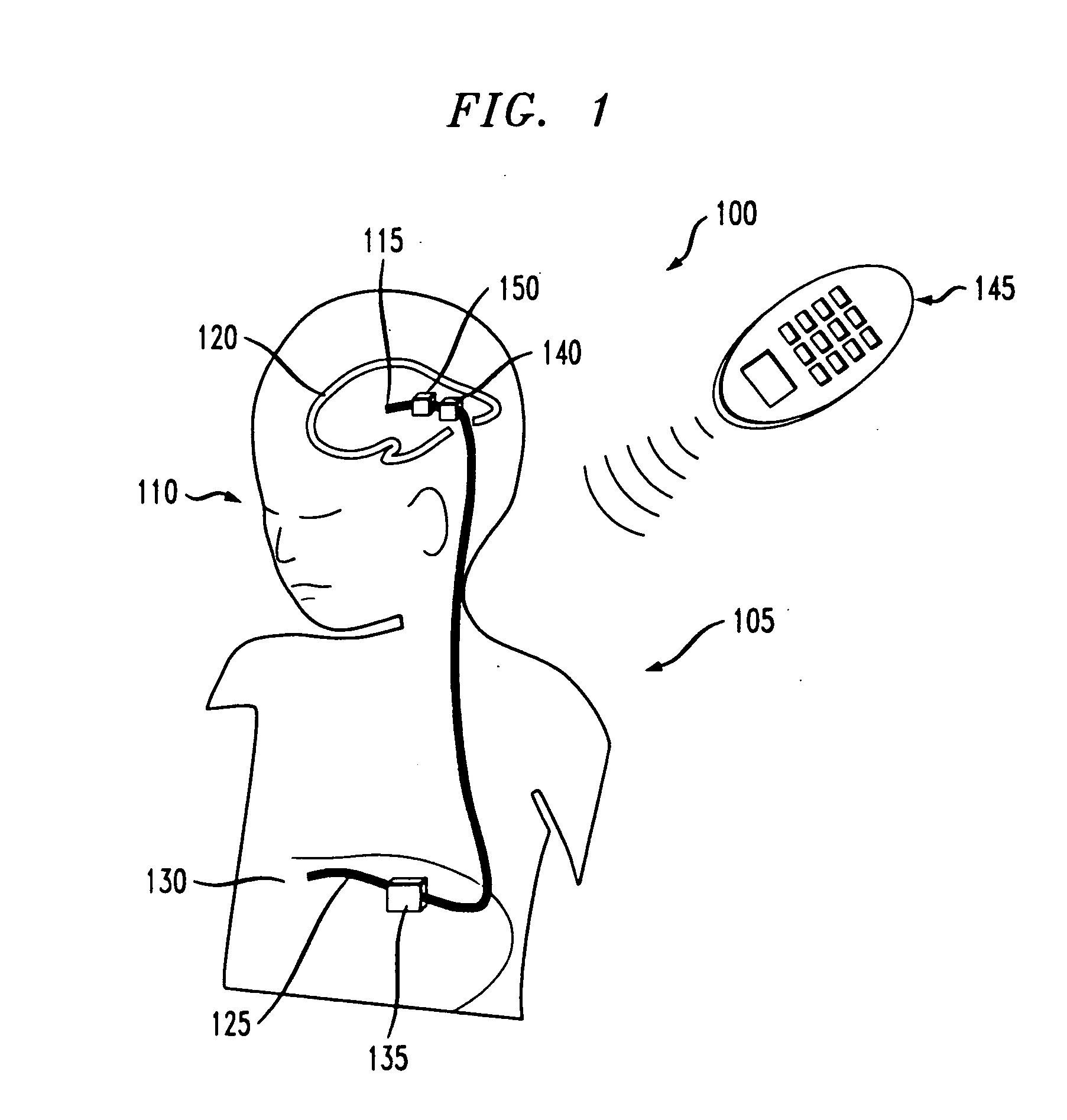
[0027]FIG. 1 is an exemplary system 100 including an implantable shunt apparatus 105 implanted within a hydrocephalus patient 110. Shunt apparatus 105 includes a proximal, head or ventricular catheter 115 installed in a ventricular cavity 120 of the patient 110, and a distal, peritoneum or drainage catheter 125 disposed in the peritoneum 130 of the patient 110. Extending between the ventricular and drainage catheters 115, 125 is a programmable valve apparatus 135 for regulating the flow of CSF into and out of the ventricular cavity 120 of the patient 110. The programmable valve apparatus 135 may be disposed anywhere along the fluid pathway of the proximal catheter 115, the distal catheter 125 or therebetween. Preferably, programmable valve apparatus 135 is located within the peritoneal cavity of the patient 110, as illustrated in FIG. 1, so that size constraints for the programmable valve apparatus 135 are minimized (e.g., larger valves can be implanted within the peritoneum than ad...


PUM


Abstract

An electrokinetic actuator for fluid flow titration including two chambers separated from one another by a porous dielectric disposed therebetween. A plurality of electrodes are disposed about a perimeter of the first and second chambers. Polar electrolyte disposed within the actuator is able to pass through the porous dielectric between the first and second chambers upon the application of an electric field or electric potential to the plural electrodes. A mechanical valve actuation mechanism connected to the second chamber allows for fine titration of fluid flow using electro-osmosis, including full-flow and/or complete cut-off. The polar electrolyte is isolated to prohibit intermixing with a fluid being titrated (such as cerebrospinal fluid).

Description

BACKGROUND OF THE INVENTION[0001]1. Field of the Invention[0002]The present invention relates to a method and apparatus for managing hydrocephalus in a patient. More particularly, the invention relates to a method and apparatus for adjusting, controlling or programming the drainage rate of cerebrospinal fluid (CSF) in a hydrocephalus patient. Even more particularly, the invention relates to a shunt system for varying the opening pressure and / or diameter of the shunt and thus controlling the rate of fluid flow (drainage) of cerebrospinal fluid from a ventricular cavity.[0003]2. Description of Related Art[0004]Hydrocephalus is a condition afflicting patients who are unable to regulate cerebrospinal fluid flow through their body's own natural pathways. Cerebrospinal fluid (CSF) is normally produced by the choroid plexus of the brain and carries essential nutrients, hormones, and other cellular components to various portions of the brain as the fluid circulates through the ventricular s...

Claims


Application Information

Patent Timeline
Patent Type & Authority Applications(United States)
IPC IPC(8): A61M1/00
CPCA61M27/006
Inventor MAUGE, CHRISTOPHE P.VENUGOPALAN, RAMAKRISHNA
Owner CODMAN NEURO SCI
Why Eureka
Try Eureka