Integrated sewage treatment plant
Inactive Publication Date: 2011-07-07
KOLESNIKOV VLADIMIR PETROVICH 50 +1
14 Cites 25 Cited by
AI-Extracted Technical Summary
Problems solved by technology
At the same time application of a single combined plant being a single unit is irrational for sewage treatment within the capacity range between 100 and 50,000 m3/day since the hydrodynamical mode control of the plant becomes more complicated and a repair shutdown of some elements is impossible.
At the same time, as there appears a layer of attached microflora on the inside surface of the fittings (β≈1.5 mm), the fittings diameter making 20 to 35 mm and their length exceeding 6 diameters, as well as due to the claws, abruptly falls the fittings' delivery capacity and raises their obstruction probability, which demands frequent cleaning.
However application of man-made dielectric materials like fiberglass, ceramoplastic, plastics, fails to provide...
Benefits of technology
At the same time, the character of the invention is as follows: above the rollers there are biological feed blocks made of plastic plates with 3 to 30 mm holes and 5 to 50 m...
Abstract
An integrated sewage biochemical treatment plant containing mechanical treatment devices, a sewage-and-sludge mixing chamber with a circulation pump and a combined biological treatment device, includes a plane feed biofilter, a spray line, collecting trays and drain collectors connected to water-jet aeratic columns sunk in the aeration zones, and aftertreatment devices. The combined biological treatment device whose capacity is 5 to 15,000 m3/day has a biofilters spray line that includes trays with emptying fittings and reflecting disks, the distance from the trays emptying fittings upper ends to the disk reflectors is 0.8 to 2 m, and the distance between the trays centers and the distance between the trays fittings axes is 0.6 to 1.8 m.
Application Domain
Treatment using aerobic processesUsing liquid separation agent +13
Technology Topic
Water jetSewage +6
Image
Examples
- Experimental program(1)
Example
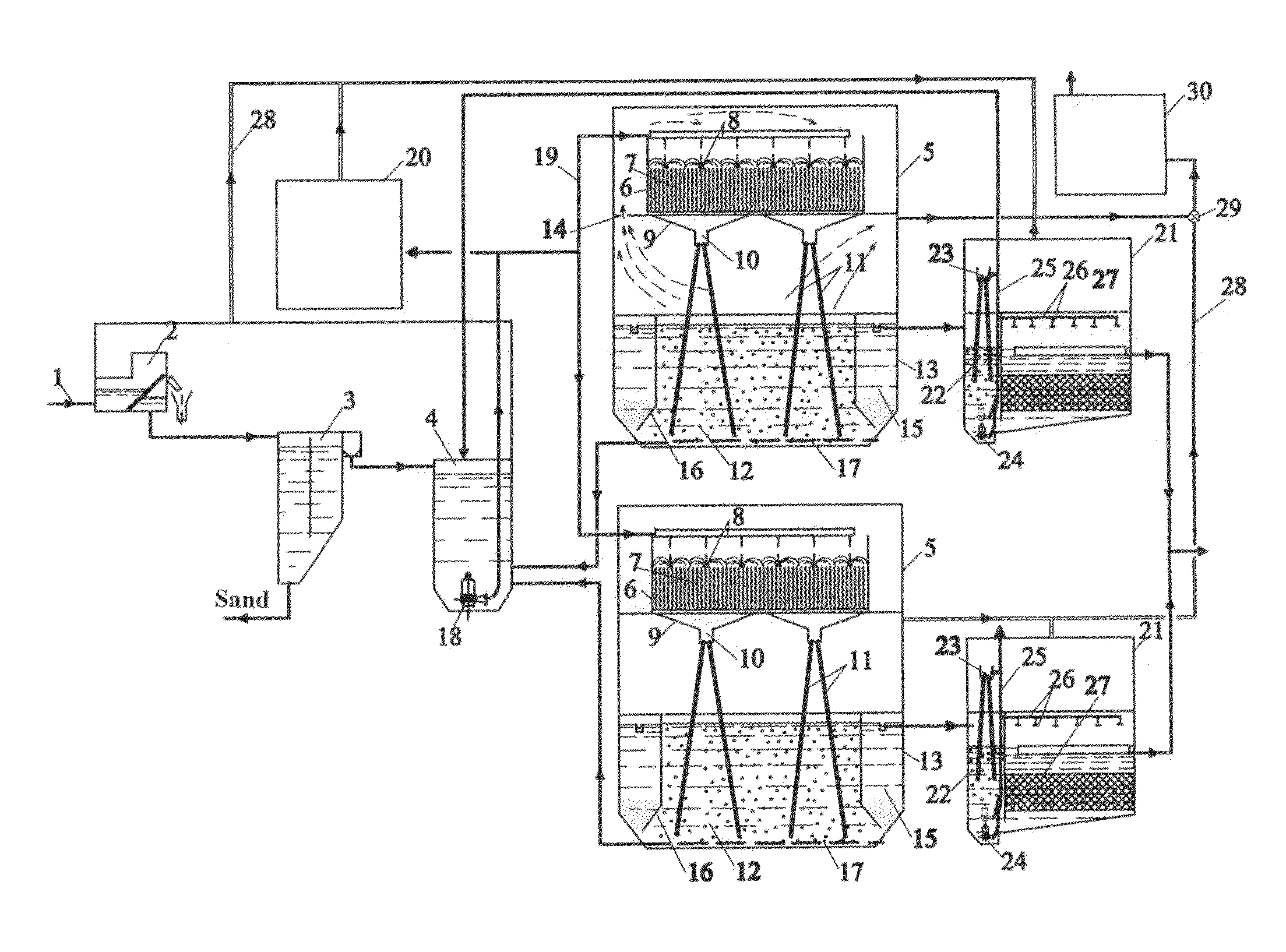
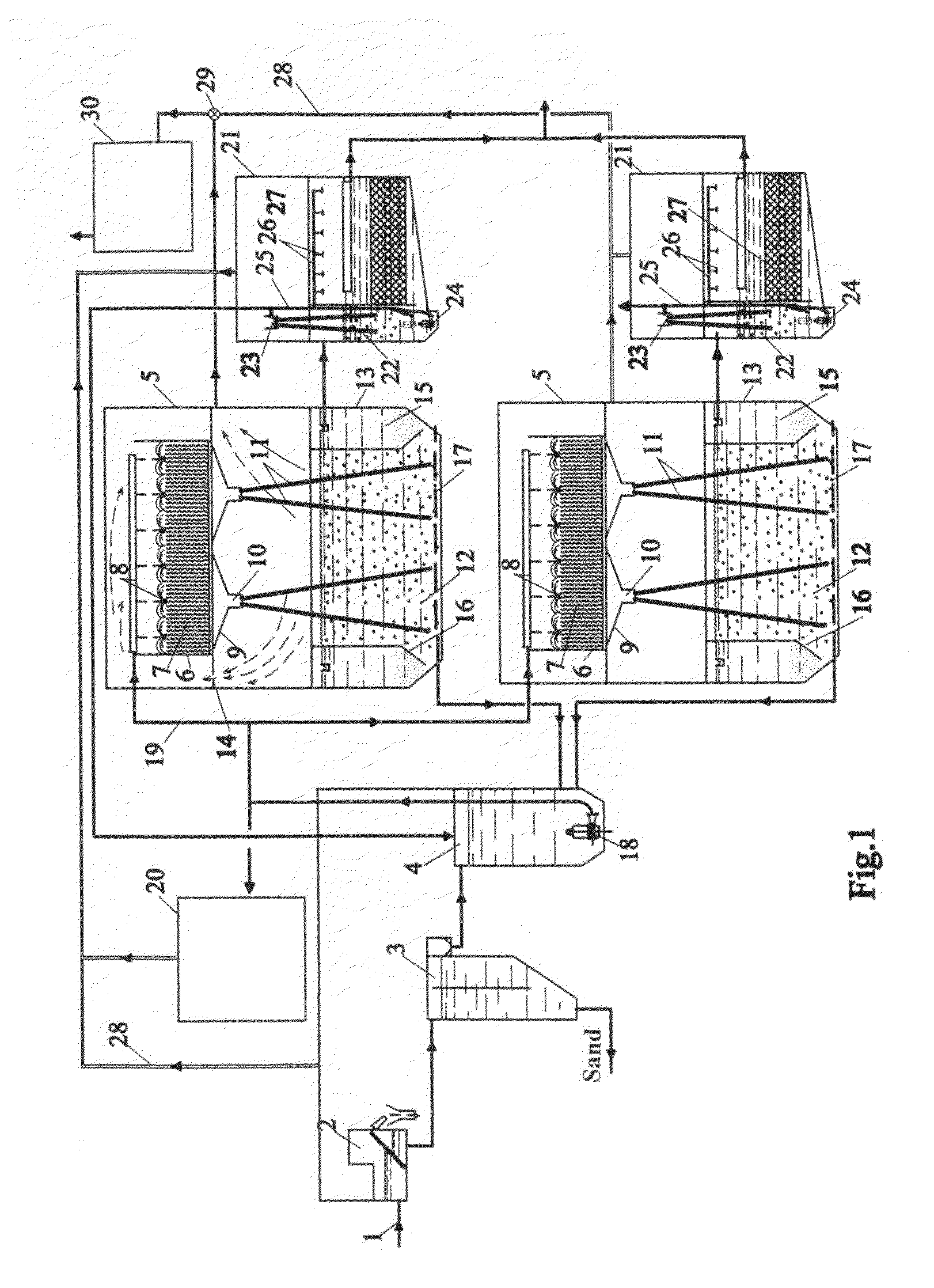
The plant for deep biochemical treatment of the sewage whose BOD reaches 1.000 mg/dm3 and suspended matters 700 mg/dm3, includes sewage feeding pipeline 1 connected to integrated mechanical treatment device 2 which is in its turn connected by a pipeline to vertical sand catcher 3. The collecting tray of vertical sand catcher 3 is connected by a drain pipeline to mixing chamber 4 combined with biological treatment devices 5. Combined biological treatment devices 5 consist of biofilters 6 with feed 7 provided with spray lines 8, collecting trays 9, and drain collectors 10. The drain collectors have aeratic columns 11 attached to them, which are sunk in aeration zones 12 of aeration tank-settlers 13. The partition separating the biofilter space from the air-tank separator space, should have valves or holes for air bypass 14. Aeration settling tanks 13 of aeration zones 12 are separated from settling zones 15 by partitions 16. The outer perimeter of the conic part of the bottom of air-tank separator 13 has sludge draining pipeline 17. Sludge draining pipelines 17 are connected to mixing chamber 4 that has circulation pump 18. Head pipeline 19 is connected to both spray lines 8 of combined biological treatment devices 5 and to excess sludge treatment device 20.
The collecting trays mounted in settling zones 15 are connected by a gravity pipeline with bioreactors 21. The bioreactor includes aeration chamber 22 with water-jet aerator 23 and pump 24. In its turn, pump 24 is connected to head pipeline 25 with water-jet aerator 23, mixing chamber 4 and spray line 26 of bioreactor 21. Aeration chamber 22 is separated by a partition from the sunk filter containing feed 27. Combined biological treatment devices 5 and bioreactors 21 are connected by air ducts 28 to fan 29 of used air treatment device 30.
Biofilter 6 spray line structure includes head pipeline with shutter 31, distributing trays 32 with gates 33, emptying fittings 34 and reflecting disks 35. Primary emptying fittings 34 have training plates 36 before them. Trays 32 are equipped with helium-neon lasers 37.
The bottom of drain collector 10 has welded sockets 38 whose lower parts have screwed-in aeratic columns 11, and upper parts have fittings 39. During pure water hydraulic testing, they mark the water level upon the fittings, then the fittings are screwed out, beveled and then screwed in sockets 38 again. Fittings 39 have heliciform hollows. The drain collector is equipped with training reflector 40 and actuator access 41.
The biofilters feed is made of corrugated ceramic sheets 42 with a frame of parallel and wavy longitudinal bands 43. Some part of longitudinal bands 44 are shaped as wavy partitions. The surface of sheets 42, except for bands 43, is characterized by evident coarseness, i.e. claws 45.
The artificial feed for biofilters may be feed elements 46 made as spheres with cavities on their surface 47, whose axes cross in the center of the sphere.
The combined biological treatment devices have a bottom of air-tank separator 13 separated into cells by triangular rollers 48 that have blocks with biological feed 49 above them. The flat sections of aeration tank 13 bottom have aeratic columns 50. The outer perimeter of the conic part air-tank separator 13 bottom has sludge draining pipeline 17 with evenly located holes or fittings 51.
The collecting tray of air-tank separator 13 is connected by a pipeline to bioreactor 21. Artificial feed 27 of bioreactor 21 is made of plastic or ceramic sheets 52 that have pivots or plates 53 attached to them. The sheets are made with holes 54. The sheets, pivots or plates have claws 55.
The pending variant of a plant for integrated treatment of household and industrial sewage with the content of organic impurities in BOD making up to 1,500 mg/dm3, suspended matters up to 700 mg/dm3, total sulphuretted hydrogen and hydrosulfides, ammonium nitrogen up to 100 mg/dm3, also includes sewage driving pipeline 1, integrated mechanical treatment device 2, sand catcher 3, and mixing chamber 4 with circulation pump 18 installed inside it. Mixing chamber 4 is connected by a free-flow pipeline to first combined biological treatment device 56. In its turn, the collecting tray of combined device 56 is connected by a pipeline to mixing chamber 57 of second biological treatment device 58. Pipeline 59 running to mixing chambers 4 and 57 connects mixing device tank 60 with hydrogen peroxide solution. Head pipeline 61 of circulation pump 18, mounted in mixing chamber 4, is connected to spray line of the biofilter of combined biological treatment device 56, mixing chamber 57 of device 58 and mixer 62. Biofilter of device 56 is filled with feed of spherical elements 46. Head pipeline 63 of circulation pump 18, mounted in mixing chamber 57, is connected to biofilter spray line of device 58 and to mixing chamber 4. Head pipeline 63 is connected to mixer 62 mounted at the clarified liquid driving pipeline, and to excess sludge treatment device 20. Mixer 62 also has coagulant solution feeding pipeline 64 running from mixing device tank 65 connected to it. In its turn mixer 62 is connected by a pipeline to denitrifier with mechanical mixer 66. The collecting tray of the denitrifier settling zone is connected to bioreactor aeration chamber 21 with artificial feed 27. In its turn, the bioreactor is connected to sorption filter 67. Envisaged is disinfection and deodoration of the biochemically used air in device 30.
In case of purifying industrial sewage whose organic impurities make in BOD 1,500 to 3,000 mgO2/dm3, suspended matters up to 1,500 mg/dm3 and fats up to 300 mg/dm3, the flow scheme includes sewage driving pipeline 1, integrated mechanical treatment device 2, sand catcher 3 and sewage pumping facility 68. The pump head pipeline is connected to the feed chamber of biocoagulator-flotator 69. In its turn, the clarified liquid pipeline is connected to mixing chamber 4 of first combined biological treatment device 56 and to mixing chamber 57 of second combined biological treatment device 58. Head pipeline 63 of circulation pump 18 mounted in mixing chamber 57, is simultaneously connected to biofilter spray line of device 58, mixing chamber 4, feed chamber of the water-jet aerator of biocoagulator-flotator 69 and to excess sludge treatment device 20.
If the organic impurities concentrations make in BOD 3,000 to 50,000 mg/dm3, the head pipeline of pumping facility 68 is connected to the feed chamber of biocoagulator-flotator 69 or to anaerobic bioreactor 70. In its turn the anaerobic bioreactor is connected to mixing chambers 4 and 57. If the flow scheme lacks biocoagulator-flotator, head pipeline 63 of circulation pump 18, mounted in mixing chamber 57, is only connected to the biofilter spray line of device 58, to mixing chamber 4, and to excess sludge treatment device 20.
Depending on the accepted flow scheme, the excess sludge pipelines run from combined biological treatment devices 5, 58, denitrifier 66, biocoagulator 69, and anaerobic bioreactor 70 to thickener 71 of excess sludge treatment device 20. The same way runs reagents (coagulant and/or flocculant) delivery line 72. The thickened settlings pipeline is connected to belt filter press 73 which is in its turn connected to grainer 74, where also connected is organic and/or mineral additives delivery line 75. The granule driving device is connected to roller conveyor 76, the rollers having electric heating elements, or heating elements 77 located under the transporter. The transporter has microwave radiators 78. There also is granule collecting holding tank 79.
Used air treatment device 30 for the plants includes air ducts 28 connected to the sucking fitting of high pressure fan (HPF) 29. Head air duct of HPF 29 is in its turn connected to irrigation chamber 80 of air treatment device 30. Device 30 is provided with spray line 81 connected to circulation pump 82 whose sucking fitting is connected to its air-fit section 83. Air-fit section 83 has clip-on section 84 above it filled with artificial feed, as well as collecting tray 85 with direct air feeding pipes 86 mounted in it. Pipes 86 are 1.2 to 2.5 m long, sunk 0.4 to 0.7 m deep into the liquid of the air-fit section and filled in their lower section with small diameter pipes 87. Water-jet air ejection pipes 88 are connected to drain collector 89, mounted at a height of 0.6 to 1.8 m above the liquid and sunk in the liquid to 1 to 3 m. Air treatment device 30 has tank 90 with natrium hypochlorite solution, odorant solution tank 91 and air duct 92 connected to it. Air duct 92 is in its turn connected to water-drop eliminator 93 which is successively connected to activated carbon filter 94 and ultraviolet disinfection unit 95.
The described integrated sewage biochemical treatment plant functions as follows.
In case of integrated treatment of household and industrial sewage with the content of organic impurities in BOD making up to 1.000 mgO2/dm3, suspended matters up to 700 mg/dm3, the sewage is by pipeline 1 driven to integrated mechanical treatment device 2 with 2 to 4 mm crevices, where particulate pollutants are caught. Then the sewage gets to vertical sand catcher 3 where the sand precipitates. After that the sewage gets to mixing chamber 4, and then to combined biological treatment device 5. The sludge from aeration zones 12 gets (under hydrostatic pressure) to mixing chamber 4 through free-flow pipelines 17. In case the described sewage biochemical treatment plant employs 2 to 4 combined biological treatment devices, then it has single circulation pump 18. This is conditioned by the constructive requirements for treatment plants, handling the hydrodynamic flows in the biofilters and aeration settling tanks, as well as temporary shutdowns of some elements. A large number of combined biological treatment devices and single circulation pump 18 makes it too difficult to control the hydrodynamic mode of biofilters and aeration settling tanks. A semi-industrial investigation has shown that if the number of the combined biological treatment devices is 4 to 6, it is advisable to make the mixing chamber of the treatment plants unit with two simultaneously working pumps dividing them with leaf gate partitions.
From mixing chamber 4 the sewage is driven through head pipeline 19, by circulation pump 18, to spray line 8 of biofilters 6. Pipeline 19 also drives excess sludge to device 20. Valves 31 mounted at head pipelines control the sewage flow-rate to each distributing tray 32. As the sludge mixture gets to narrow distributing trays 32 at the initial sections, especially as circulation pump 18 is switched on, there is rough undulatory motion in the trays, which may result in the liquid run over the edges. Reduction of the liquid pressure and its flow leveling in the trays is all done with the help of gates 33. Due to the liquid high speed at the trays initial sections, hampered is the drain of the liquid to first drain fittings 34. To reduce the stream turbulence before the initial fittings, there are training plates 36 favoring the drain of the liquid to the fittings holes.
The liquid flow through the fittings is controlled by way of altering the fittings height above the trays bottoms. At the same time one should try to reduce the length of the fittings as it reduces the amount of the biomass attached inside the fittings and correspondingly raises their delivery capacity. The recommended length of the fittings mounted at the beginnings and ends of the trays is 2 to 6 diameters. The density of the falling jets is raised due to the hollows of drain fittings 34 made as 1 to 1.5 revolution spirals with a height of less than 0.7 diameters.
The optimal proportion between the consumption of power for spray line work and irrigation evenness defines the following parameters of the system: in case the distance from the upper ends of the emptying fittings of the trays of the spray line to the reflecting disks is 0.8 to 2 m, the distances between the centers of the trays and the distances between the axes of the fittings should stay within the limits of 0.6 to 1.8 m.
The biofilters feed of devices 5 is made of corrugated ceramic plates 42. Inclusion of metal compounds in the material raises the electrokinetic potential of the material adsorptive layer. Electrostatic adhesion immobilizes the colonies of microorganisms. Frame 43 of thickenings is made as parallel and longitudinal bands and longitudinal bands with outstanding wavy partitions 44 provides strength of the construction as the weight of the biomass layer grows. The attached microflora layer is directly influenced by the coarseness made as claws 45 (0.1 to 1.5 mm). Reduction of bands 43 coarseness down to 0.1 to 0.5 mm reduces cohesion with the feed material, which alongside with wavy partitions 44 favors reduction of size of the possible silting zones and excess biomass discharge.
The feed surface forms a layer of attached biomass whose thickness reaches 10 mm, which (apart from the microflora sorbing and oxidizing the organic understratum—50 to 70% of the solved organic matters) develops nitrifying and denitrifying microorganisms.
Inclusion of metal particles in feed 7 material raises the electrokinetic effect which increases the potential of the adsorptive feed layer. A semi-industrial testing showed compact biomass accumulation (whose thickness reached 5 to 7 mm) on the sheets with metal compounds electroacoustical sputtering due to implantation in the feed surface layer of various compounds like carbides, carbonitrides, intermetals, etc. These metal inclusions are catalyzers raising the dynamic activity of the microorganisms. The feed active centers sorb reacting substance molecules, their concentration raises, which positively effects the adhesion of the surface layer. Combination of the structural-mechanical, kinetic and electrical factors stabilizes nitrification and denitrification thus raising the degradation level of the nitrogen-containing impurities in the plant.
Laser radiation treatment of the circulating sewage and active sludge mixture in the biofilters spray line trays with the help of helium-neon lasers 37 in a scanning mode stimulates the growth of the active biomass bacteria, especially the growth of the nitrifying and denitrifying microorganisms. Test sludge radiation treatment with helium-neon lasers, the wave-length being 632.8 nm, during 3 minutes showed a 5.9 time growth of bacteria number within 1 hour after the treatment. Rise of the microorganisms biological activity reduces the negative effect of the microflora overload in case of an abrupt rise of organic and hydraulic plant loads.
The sewage-and-sludge mixture, after it has passed feed 7 of biofilters 6, is collected with the help of trays 9 and driven to drain collectors 10. Disorganized drain of liquid, insufficient distance between the centers of the upper cuts of aeration columns 11, deviation in the fittings heights above the drain collectors bottoms, all cause chaotic movement of liquid, which results in a lower effectiveness of air entraining in the aeration columns. That is why the upper section of the drain collectors should have training reflectors 40 to accept and drive down the liquid flow. Pressure extinction favors even liquid flow to the upper cuts of the aeration columns. The recommended distance between the columns cuts of 25 to 100 mm diameter in the upper section within the limits of 50 to 500 mm reduces the turbulence of the liquid flows in collectors 10 and favors its even distribution between the columns. Exact orientation of the upper cuts of the columns on the water level is done by way of fittings 39 screwing in and out, and beveling. Strong vortex cavities for sucking air in aeratic columns 11 are favored by heliciform inner hollows in fittings 39 since they stabilize clockwise revolutions as the liquid flows into the pipes. As shown by a semi-industrial investigation, the optimal height of rifling is between 0.5 diameter. Fittings 39 are mounted and aeration columns 11 cleaned through accesses 41.
The effectiveness of air oxygen mass transfer into the liquid and aeration zone content stirring depends on the following major factors: aeration columns diameter, liquid capacity (m3/h), proportion between the aeration columns height above the liquid and the height of the columns sunk section, aeration zone depth, columns placement in the aeration zone and air-tank separator configuration.
The aeration columns inner diameters are recommended to stay between 40 and 70 mm. 25 to 40 mm diameters are also acceptable for smaller capacity range plants, yet in this case the m3/h capacity and the amount of the involved air are especially badly influenced by the fact that the inside of the pipes biocenosis' fouling is β≈1.5 mm, due to which the pipes should be regularly cleaned. Application of 70 to 100 mm diameters (with a larger bypass through the columns) also provides a higher coefficient of mass transfer (Cs) within the pipes capacity (for example if dy is 70 mm q=9 to 19 m3/h), yet this reduces the stirring effectiveness of the whole content of the aeration zone. To provide sufficient shock of the air-water torches on the bottom, the recommended design liquid flow (m3/h) through the columns should be not less than half of the total of the minimum and maximum capacities forming vortex cavities.
Proceeding from the optimum values: power consumption for liquid circulation through the biofilter to the aeratic columns—the aeration tank—the mixing chamber, the treatment plant construction depth and aeration columns maintenance, the recommended height of the columns above the liquid level in the aeration tank for the combined biological treatment devices capacity range of 5 to 50 m3/day, is 1.2 to 1.8 m, the columns sunk section is recommended to stay between 1.5 and 2 m, while the columns lower cuts height above the bottom should stay between 0.05 and 0.2 m; if the capacity range is 100 to 15,000 m3/day, the columns upper section height should be between 2 and 3.5 m, the columns sunk section height between 2.5 and 4 m, the columns lower cuts height above the bottom between 0.15 and 0.4 m. The distance between the lower cuts of the adjacent aeration columns (25 to 100 mm) and those columns mounted diagonally should be 0.5 to 3 m. To reduce the size of the aeration tank's bottom recommended are triangular rollers 48 mounted at the flat section of the aeration zone bottom. The optimum size of rollers 48, proceeding from the conditions of the reaction zone maximum size, sludge liquid stirring effectiveness and avoidance of sludge deposition, are as follows: width 0.5 to 2.0 m; height 0.5 to 1.5 m. In case of sedimentation of sludge flakes within settling zone 15 of air-tank separator 13 there can be formed stagnant zones where the conic and flat sections of the aeration tank's bottom articulate, with further decay and emersion of defunct sludge. That is why the minimum distance from the lower ends of the outermost columns of 25 to 50 mm diameter to the corner should not exceed 0.5 to 0.7 m, while for 50 to 100 mm diameters the same should not exceed 0.7 to 1.2 m. The length of the lower leg of settling zone 15 conic part should make one half of the settling zone width plus 0.1 to 1.0 m. At the same time the distance from the bottom of the conic part of the partition separation aeration and settling zones, to the bottom should make 0.5 to 1.5 m. To prevent reduction of the shock of the gas-and-liquid flows leaving the lower ends of aeration columns 11, the sludge mixture pipeline and correspondingly deterioration of the hydrodynamical conditions of stirring the content of air-tank separator 13, pipeline 17 is mounted beyond the outward perimeter of the conic part of the air-tank separator bottom with holes or fittings 51 located under the angle of 0 to 90° to the long axis of the pipeline and at a distance of 0.2 to 1.0 m from each other.
In case followed are all the mentioned parameters of aeration columns and air-tank separator structural devices placement, the water-air torches shock on the aeration zone bottom, the hydrodynamical movement of the fluid flows, and air bubbles emersion exclude any active sludge deposition and decay.
To fasten and develop the microflora oxidizing the organic matters and carrying out nitrification, the aeration zones reservoirs of the aeration settling tanks of the combined biological treatment devices have, above rollers 48, biological feed blocks 49 made of plastic plates with holes, of 3 to 30 mm and 5 to 50 mm long bristles. Blocks 49 may also be made of ceramic sheets with holes of 3 to 30 mm and claws shaped as 5 to 40 mm long pivots or plates. The sheets, pivots or plates have evident coarseness in the form of claws. This coarseness favors immobilized microflora attachment on the feed surface. Inclusion of metal compounds in the material raises the electrostatic adhesion of microflora, which alongside with the reduction of turbulence of the liquid flows inside the feed, favors older nitirifying sludge development. Reduction of the liquid flows turbulence in the feed reduces carrying-out of the adapted active sludge. The concentration of the active biomass within sunk feed 49 may reach 10 g/dm3.
The reaction volumes of the aeration and settling zones oxidize the rest part of the organic impurities (30 to 50%) under low loads upon the sludge≈0.1 to 0.2 g·BOD/gsludge·day, mineralization of the waste biomass of the biofilters feeds. The ash content of the sludge during developed nitrification and partial denitrification equals 33 to 42%, the average water yielding capacity specific resistance is 38 to 45·10−10 cm/g. The excess sludge contains carbon, nitrogen, phosphorus and trace elements, is characterized by high mineralization, fine water yielding capacity, does not decay and thus, after additional treatment, may be used as a fertilizer.
The purified water is drained from settling zones 15 to the collecting trays and driven to integrated sewage afterpurification bioreactors 21, where, in aeration chambers 22, is additionally saturated with dissolved oxygen with the help of water-jet aerators 23 and circulation pumps 24. Pumps 24 are equipped with flexible hoses controlling the sinking depth. After that the water passes feed layer 27.
The bioreactors feed may be made of plastic or ceramic plates 52 with attached 10 to 100 mm long pivots or plates 53 and 3 to 30 mm diameter holes 54. These holes optimize the hydrodynamic mode of the liquid inside the bioreactor at biomass swells (which raises the feed volume application factor). The feed surface develops specific biocenosis using during its lifetime the residual concentrations of the organic matters and ammonium nitrogen. The coarseness (claws 55) favors immobilized microflora better attachment. To intensify attached biomass formation on the feed surface, the feed is activated by way of inclusion of metal compounds into its composition. The liquid driven from devices 5 to bioreactors 21 also contains light flakes of defunct sludge. As the water moves through feed 27, the flakes are physically caught due to liquid filtering through biocenosis, which is favored by smaller distances between the pivots or plates in the feed upper section (3 to 5 mm) and formation of a 1 to 1.5 mm thick microflora layer in them.
The attached microflora formed on the surface of feed 27 sorbs and oxidizes the residual organic impurities and further transforms the nitrogen-containing compounds. These biological processes are supplied with required air oxygen with the help of pump 24 and water-jet aerator 23. As suspended matters accumulate, bioreactors 21 are partially emptied and the feed regenerated with the help of spray line 26 and pump 24. Then the pump is sunk in the bioreactor pit and the liquid pumped away through pipeline 25 to mixing chamber 4 of devices 5.
Pipeline 19 delivers all excess sludge to excess sludge treatment device 20. The air from integrated mechanical treatment device rooms 2, sand catchers 3, combined biological treatment devices 5, bioreactors 21 and devices 20, is taken away by fan 29 and driven to used air treatment device 30.
In case of integrated treatment of household and industrial sewage with the content of organic impurities in BOD making up to 1,500 mgO2/dm3, suspended matters up to 700 mg/dm3, sulphuretted hydrogen and hydrosulfides, ammonium nitrogen up to 100 mg/dm3, the sewage is driven through pipeline 1 to integrated mechanical treatment device 2, and then to sand catcher 3. From the collecting tray of sand catcher 3 the waste water gets to mixing chamber 4 where it is mixed together with the circulating sludge liquid of first combined biological treatment devices 56 and with 30 to 35% hydrogen peroxide solution driven through pipeline 59 from mixing device tank 60. Then the mixture of sewage, sludge and reagent is pumped by circulation pump 18 to head pipeline 61 to the spray line of biofilter devices 56. After that the liquid passes the feed of biofilter 46, is drained to aeratic columns, and then mixed with the active sludge of the air-tank separator. Introduction of a reagent in device 56 oxidizes sulphuretted hydrogen and hydrosulfides turning them into colloid sulphur and sulphates and reducing their inhibitory effect on the biocenosis. Above all, according to the investigations, the concentration of the oxygen dissolved in the waste water rises up to 5 to 6 mg/dm3, which intensifies biological treatment. Introduction of hydrogen peroxide in the mixing chamber of the first combined biological treatment device is advisable if the restored sulphur compounds concentration exceeds 20 mg/dm3. The hydrogen peroxide doze was empirically defined taking into account the initial concentration of the restored sulphur compounds, and it makes 10 to 100 mg/dm3.
In case of multiple irrigations and contacts between the waste liquid and the biocenosis of the biofilter feed surface, and active sludge of the reaction zone of the air-tank separator (1 to 3 hours), sulphuretted hydrogen undergoes degasification, the restored sulphur compounds are reagentally and biochemically oxidized, the organic impurities are biodegraded 50 to 70% in BOD, and there is partial denitrification (10 to 15%). The formation of a specific microflora (sulphur-bacteria, filamentous, thionyl microorganisms, anammocs-bacteria) sorbing and oxidizing hydrosulfides, as well as carrying out partial denitrification in biofilter devices 56, is favored by spheric elements 46 with 8 cavities 47 whose axes meet in the center of the sphere. Microflora attachment and development is favored by the coarseness of the feed elements surface (0.1 to 1.5 mm), reduction of turbulence and longer time of contact between the defluent liquid and the biomass of the feed reservoirs. Advisable also is to use elements with 4 to 10 cavities. Long-term industrial investigations have shown that the optimal diameter of the spherical elements is 70 mm as in this case the feed is not silted. At the same time, as purified is sewage with the content of the organic impurities in BOD less than 100 mg/dm3, one can use feed elements of a minimum diameter of 35 mm, even if BOD concentrations exceed 300 mg/dm3 to 100 mm. In the production of elements for electrostatic adhesion and catalytic effect on microflora, it is advisable to use clays with a high iron and aluminium content. The ceramic feed material may additionally include high-melting metal compositions.
Pumping into inlet chamber 4 of first device 56 of some part of the circulation liquid from head pipeline 63 of second device 58 reduces organic matters load on the biocenosis of first device 56 (thus microflora overload is avoided). The excess biomass containing significant amounts of adsorbed unoxidized organic matters of device 56 is mineralized in device 58. With this purpose the introduced sludge is pumped through pipeline 61 to mixing chamber 57 of device 58.
After that the clarified liquid of settling zone device 56 is driven to mixing chamber 57 of device 58. At the same place, through pipeline 1, driven is some part of the initial sewage, and through pipeline 59 driven is hydrogen peroxide solution of reservoir 60. Introduction of hydrogen peroxide to mixing chamber 57 of second device 58 is advisable in case the residual restored sulphur compound after the first combined device exceeds 5 mg/dm3. Then the mixture of sewage, sludge and reagent is pumped through head pipeline 63 with the help of circulation pump 18 to the spray line of device 58 biofilter, where the remaining part of the organic impurities is further sorbed and oxidized. At this stage and in case the organic matters load on the sludge is low (0.05 to 0.2 kg/BOD per 1 kg of ash free substance), there is complete organic impurities oxidation and fine nitrification and partial denitrification of nitrogen-containing compounds. The period of the sewage stay is 4 to 7 hours. To activate biological treatment in case of microflora overload within device 56, 10 to 30% of the circulating liquid is pumped from head pipeline 63 of combined biological treatment second device 58 to mixing chamber 4 of device 56. If the content of ammonium nitrogen in the initial sewage exceeds 30 mg/dm3, the denitrifier 66 substratum is some part of sludge mixture of device 58, which is pumped through head pipeline 63 to mixer 62. The sludge liquid is also partially pumped from pipeline 63 to excess sludge treatment device 20.
The biofilters feed of devices 56, 58 may be made of spherical elements 46 and/or corrugated ceramic plates 42.
To attach and develop the microflora oxidizing hydrosulfides and carrying out nitrification, biological feed blocks 49 should be installed within the reservoirs of aeration settling tanks zones of devices 56 and/or 58.
After that the purified waste water of the settling zone of device 58 gets to mixer 62, where, by circulation pump 18, also driven is the sludge liquid (substrate) of mixing chamber 4 of first device 56, or substrate of mixing chamber 57 of second device 58. Mixer 62 may accept 2 to 5% of the coagulant solution for reagent removal of phosphates. The resulting mixture is driven through the pipeline to the denitrifier with mechanical mixer 66. When in the denitrifier, nitrates nitrogen is transformed into volatile nitrogen forms. Soluble phosphates interact with the coagulant hydrolysis product, which results in the formation of coagulate precipitating together with active sludge in the lower section of denitrifier 66. The result is that the waste water, after is has passed the denitrifier, reduces its nitrite and phosphates nitrogen concentrations. An experimental investigation has demonstrated that the most effective coagulant is aluminium-containing coagulant modified by activated carbon. The coagulant doze in Al2O3, in view of the amount destined for the active sludge sorbtion of the coagulant hydrolysis products, makes 20 to 60 mg/dm3.
Coagulant introduction further intensifies dehydration in excess sludge treatment device 20.
After that the waste water is driven through the collecting tray of denitrifier 66 by pipeline to aeration chamber 22 of bioreactor 21 equipped with water-jet aerator 23 where the volatile nitrogen is blown away and the liquid saturated with air oxygen. Then, as the liquid moves bottom-up, it contacts with artificial feed 27.
If the purification quality is to be raised in BOD and suspended matters up to 3 mg/dm3, phosphorus up to 0.2 mg/dm3, and ammonium nitrogen up to 0.4 mg/dm3, the treatment flow scheme is added by sorption filter 67. The waste water is driven to afterpurification filter 67 with a two-layer feed. Contacting with the first layer, the biologically purified waste water is freed from fine particles like sludge flakes and alumophosphates hydroxocomplexes; contacting with the other layer removes dissolved orthophosphates resulting from chemical adsorption due to the intermolecular interaction between orthophosohates and the feed grains surface. The feed materials of bioreactor 21 and filter 67 are regularly regenerated with pumps 18.
The sludge and settlings of bioreactor 21 and filter 67 are driven away through the head pipeline of excess sludge treatment device 20 or in the mixing chamber of devices 56 and 58.
In case of treatment of industrial sewage with the content of organic impurities in BOD making 1,500 to 3,000 mgO2/dm3, suspended matters up to 1,500 mg/dm3 (ash content exceeding 30%), and fats up to 300 mg/dm3, the sewage being first mechanically purified in devices 2, 3, is driven by pump station 68 to biocoagulator-flotator 69.
Advisability of including biocoagulators in the treatment flow scheme is stipulated by the following: suspended matters precipitation (50-70%); partial removal of organic impurities (15-20%) due to the sorption properties of the removed excess sludge, flocculation and flotation; excess biomass and impurities compaction (7 to 15 g/dm3) before these are driven to the mechanical dehydration section; partial organic loads and pH averaging.
The inlet chamber of the water-jet aerator of biocoagulator-flotator 69 also receives, through pipeline 63, the active sludge of mixing chamber 57. The feed chamber has 0.3 to 1.5 m long aeratic columns attached to it, their canting angle to the pintle being 0 to 50° C. equipped with tangentional fittings. The liquid flow brings, through the aeratic columns, air qb≈0.8 m3/m3 liquid (per a single column). The sewage-and-sludge mixture is revolved within biocoagulator-flotator 69 with the help of columns with tangentional fittings. The sludge-to-water contact lasts within the flocculation chamber 8 to 20 min. Those fat particles floating with the air bubbles are removed by the liquid undulating movement to the collecting tray. The effectiveness of fat removal in the biocoagulator-flotator makes 60 to 80%. After the flocculation chamber, the sludge mixture moves through the expansion cone to the settling zone where the sludge mixture is divided. After that the settled waste liquid is driven to the mixing chambers of combined biological treatment devices 56 and 58 where the remaining fats (60 to 100 mg/dm3) and dissolved organic matters are sorbed and oxidized.
In case of treatment of industrial sewage with the content of organic impurities in BOD making 3,000 to 50,000 mgO2/dm3, suspended matters up to 1,500 mg/dm3, the sewage, after its mechanical treatment, is driven through the pipeline to biocoagulator-flotator 69 and/or directly to the lower section of anaerobic bioreactor 70.
The pipes driving liquid to device 70 are evenly placed along the perimeter, the distances from the conic part of the bottom being 100 to 200 mm, which provides even distribution of upward flows within bioreactor 70 and washing of the settling anaerobic sludge. The incoming sewage contacts with the sludge mixture (biomass concentration≈10 to 20 g/dm3) in a counterflow mode during 1 to 8 hours. The sewage-and-sludge mixture is stirred with the help of the circulation pump intaking the settling sludge from the lower section of the anaerobic bioreactor and driving it through the pipeline to the upper section of the reactor. The sludge is introduced and its content stirred with the help of a distribution system consisting of several 0.3 to 2.5 m long pipes, their canting angle to the pintle being 0 to 70° C. equipped with tangential bends revolving the sludge mixture in the reactor.
The anaerobic sludge sorbs and oxidizes 50 to 70% of the organic impurities and 60 to 80% of the suspended matters. Methane fermentation raises the concentration of sulphuretted hydrogen and hydrosulfides up to 100 mg/dm3 and decreases the environment pH down to 4-5.
After that the liquid driven from the anaerobic bioreactor is directed through the pipeline to the mixing chamber of combined biological treatment devices 56, 58. Then the sewage-and-sludge mixture, through head pipeline circulation pump 18 mounted in the mixing chamber of first combined device 56, is driven to the spray line of devices 56, as well as to the mixing chamber of second combined device 58. Through the head pipeline of circulation pump 18 mounted in mixing chamber 57 of second combined devices 58, the sludge mixture is driven to the spray line of device 58, to mixing chamber 4, and to excess sludge treatment device 20. To the same places also driven is the condensed precipitate of the conic part of biocoagulator 69 and/or anaerobic bioreactor 70.
The design features of combined biological treatment devices, the two-stage scheme with successively connected combined biological treatment devices and hydrogen peroxide application provide complete removal of sulphuretted hydrogen and hydrosulfides.
Negative pH effect on aerobic purification successively decreases due to waste liquid repeated dilution with circulating active sludge in the mixing chambers and sludge mixture contacting first with the biocenoses of the biofilters adapted to low pH values.
Depending on the accepted treatment flow scheme, device 20 has excess sludge pipelines running to it from combined biological treatment devices 5, 58, anaerobic bioreactor 70 and denitrifier 66. There is also a possibility of connecting biocoagulator 69 to device 20. The pipelines are connected to thickener 71 of devices 20. If there is a need to raise the effect of sludge and settlings thickening, to the thickener also connected is coagulants and/or flocculants delivery line 72. Then the condensed precipitate is driven to band filter press 73, where formed is cake of predetermined humidity of 75 to 85%. Dehydrated cake goes to grainer 74 where also connected is delivery line for organic and/or mineral additives 75. The organic and mineral additives may be saw dust, sunflower seed husk and mineral fertilizers. The grains get from 74 to transporter rollers 76 with built-in electric heating elements 77. Heating elements 77 may also be placed under the roller transporter and heat the grains. Revolving rollers have claws moving the grains. Microwave radiators 78 mounted above the transporter additionally dry and dehelmintize the grains content. After that the grains are poured in collecting tank 79.
The air from the mechanical, biological treatment and aftertreatment devices is driven by fan 29 to air treatment device 30 where it initially passes through irrigation chamber 80 where it contacts with sodium hypochlorite solution fed to irrigation system 81 by circulating pump 82. Irrigation and movement of air and natrium hypochlorite solution drops through the artificial feed of section 84 results in interphase contacting. After that the air, through direct supply pipes 86, is driven to bubble section 83 where air bubbles once again contact the solution. Availability, in the lower section of pipes 86, of smaller diameter pipes 87, divides the outlet air into little bubbles, which favors better surface contacting between the phases. The rising air, by air duct 92, gets to drop separator 93. As the liquid flows through collecting tray 85 to drain collector 89 and after that to water-jet air ejection pipes 88, some part of the air getting to device 30 (0.5 to 0.7 m3/m3 of the liquid) is sucked in the pipes. Further emersion of the air bubbles stirs the contents of air-fit section 83 and intensively renews the gas-to-liquid contacting surface of the whole contents. New solution is injected from hypochlirite tank 90. In case of emergency, odorant can be delivered from tank 91. The air, after its wet purification in air duct 92, gets to drop separator 93. After that the air is driven for aftertreatment to ultraviolet disinfection devices 95.
A malfunction in sewage biochemical treatment may result in a whole process breakdown and consequently in objectionable odors. That is why, as the treatment plant is in emergency operation, the air treatment flow scheme should include activated carbon filters 94 which, together with odorants, completely exclude any objectionable odors. Ejection of a little part of small hypochlorite droplets from drop separator 93 prevents formation of microflora within the activated feed pores. Heating (feed regeneration) usually takes place in the post-fault period. After the air has passed carbon filters, it is driven to ultraviolet disinfection devices 95.
It is advisable to use the integrated sewage biochemical treatment plant for the purification of household and industrial sewage produced by dwelling-houses, villages, towns and cities, meat-packing plants, fish processing plants, canneries, cattle breeding farms, yeast factories, breweries, sugar-mills, pulp and paper mills, chemical and microbiological enterprises, etc.
The level of purification of household and industrial sewage with BOD making 100 to 1,500 mg/dm3, suspended matters up to 700 mg/dm3, is 98 to 99%. In case the sewage BOD is only 50 to 100 mg/dm3, the plant's biofilters perform sorption and oxidation of 70 to 80% of the organic impurities. The biomass separated from the biofilter feed replenishes the suspended sludge layer in the air-tank separator, which brings the purification effect up to 99%.
As shown by semi-industrial and industrial testings, the pending integrated biochemical treatment plant provides complete removal of sulphuretted hydrogen and hydrosulfides, reduction of the ammonium nitrogen concentration from 100 mg/dm3 down to 0.5 mg/dm3 and phosphorus down to 0.2 mg/dm3.
Inclusion of biocoagulators-flotators in the flow scheme of sewage two-stage biological treatment with combined devices brings the parameters of concentrated sewage (BOD content up to 3,000 mg/dm3, fats up to 300 mg/dm3 and suspended matters up to 1,500 mg/dm3) to the values equaling 10 to 15 mg/dm3.
Inclusion of anaerobic bioreactors in the flow scheme of the integrated sewage biochemical treatment plant provides effective strong sewage purification (BOD content up to 50,000 mg/dm3).
The proposed plant solves a complex problem of sewage treatment, used air treatment and valuable granulated fertilizer production.
As compared to conventional aeration plants, the consumption of the power needed for biochemical treatment is 2 to 3 times less; the personnel reduces by 50 to 70%; the treatment plants area is also 3 times less, and the sanitary-hygienic zone may be 50 to 100 m depending on the plant capacity.
Thus, the invention relates to the purification of household and industrial sewage with the content of organic impurities in BOD making 50 to 50,000 mg/dm3, suspended matters from 50 to 1,500 mg/dm3, fats up to 300 mg/dm3, hydrosulfides and sulphuretted hydrogen, ammonium nitrogen up to 100 mg/dm3 and can be used for the treatment of the waste water produced by dwelling-houses, villages, towns and cities, meat-packing plants, fish processing plants, canneries, cattle breeding farms, yeast factories, breweries, sugar-mills, pulp and paper mills, chemical and microbiological enterprises, etc.
The objective as viewed by the designers of the new integrated sewage biochemical treatment plant was to create such variants that would provide efficient and steady quality of purification of sewage characterized by high contents of organic impurities, sulphuretted hydrogen, hydrosulfides, ammonium nitrogen, and would raise the environmental safety of the purified sewage.
The technical result achieved by the designers as they solved the problem set forth, was a high level of sewage and used air purification, as well as valuable granulated fertilizer production.
The character of the invention is that the integrated sewage biochemical treatment plant containing mechanical treatment devices, a sewage-and-sludge mixing chamber with a circulation pump and a combined biological treatment device, including a plane feed biofilter, a spray line, collecting trays and drain collectors connected to water-jet aeratic columns sunk in the aeration zones, and aftertreatment devices; the combined biological treatment device whose capacity is 5 to 15,000 m3/day has a biofilters spray line that includes trays with emptying fittings and reflecting disks, the distance from the trays emptying fittings upper ends to the disk reflectors is 0.8 to 2 m, and the distance between the trays centers and the distance between the trays fittings axes is 0.6 to 1.8 m. In case the aeration columns diameter is between 25 and 100 mm, their height above the liquid level in the aeration settling tanks is 1.2 to 3.5 m, and the sinking height under the liquid level is 1.5 to 4 m. At the same time the distance between the columns upper cuts is 50 to 500 mm and the distance between the lower cuts of the aeration columns is 0.5 to 3 m.
PUM
Property | Measurement | Unit |
Temperature | 0.0 ~ 90.0 | °C |
Temperature | 0.0 ~ 70.0 | °C |
Temperature | 0.0 ~ 50.0 | °C |
Description & Claims & Application Information
We can also present the details of the Description, Claims and Application information to help users get a comprehensive understanding of the technical details of the patent, such as background art, summary of invention, brief description of drawings, description of embodiments, and other original content. On the other hand, users can also determine the specific scope of protection of the technology through the list of claims; as well as understand the changes in the life cycle of the technology with the presentation of the patent timeline. Login to view more.