Capacitive micromachine ultrasound transducer

Active Publication Date: 2011-07-07
KONINKLIJKE PHILIPS ELECTRONICS NV
View PDF4 Cites 39 Cited by
  • Summary
  • Abstract
  • Description
  • Claims
  • Application Information

AI Technical Summary

Benefits of technology

[0031]It may be seen as a main essence of the present invention to prevent the charging of transducers. The prevention of charging results in stable characteristics of the transducer. The charging is prevented or at least reduced by arrangement of at least one barrier. This barrier can be realised by an additional dielectric layer. The barrier

Problems solved by technology

However, charging is a known disadvantage of capacitive micromachined ultrasound transducers of the prior art and often

Method used


Image

  • Capacitive micromachine ultrasound transducer
  • Capacitive micromachine ultrasound transducer
  • Capacitive micromachine ultrasound transducer

Examples


Embodiment Construction

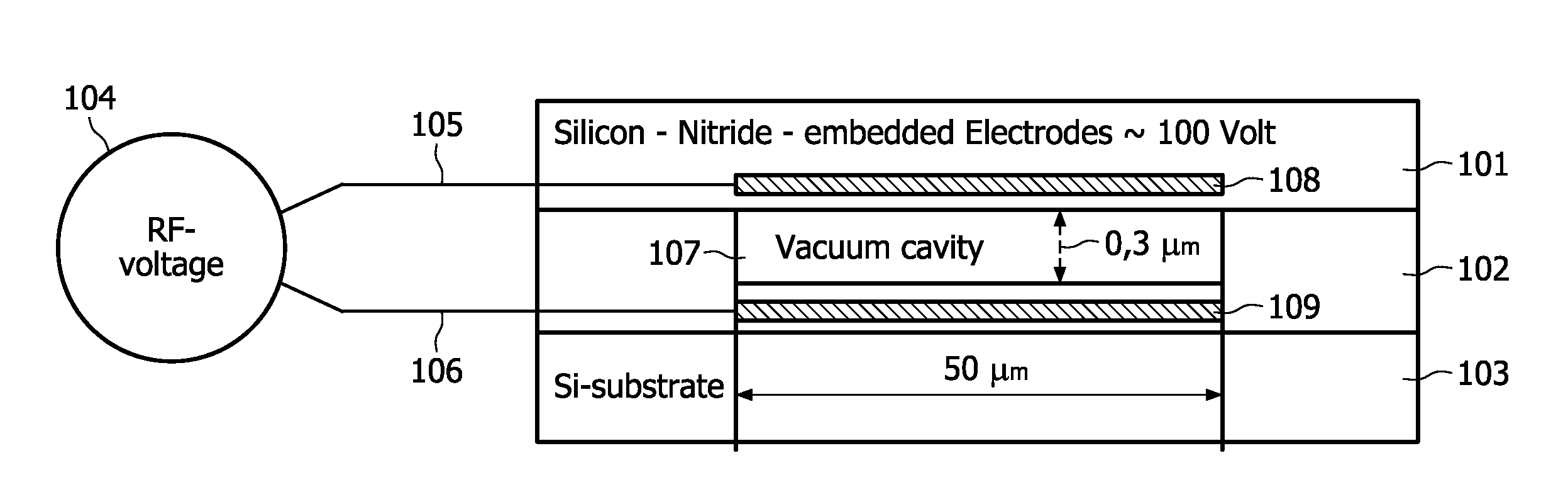
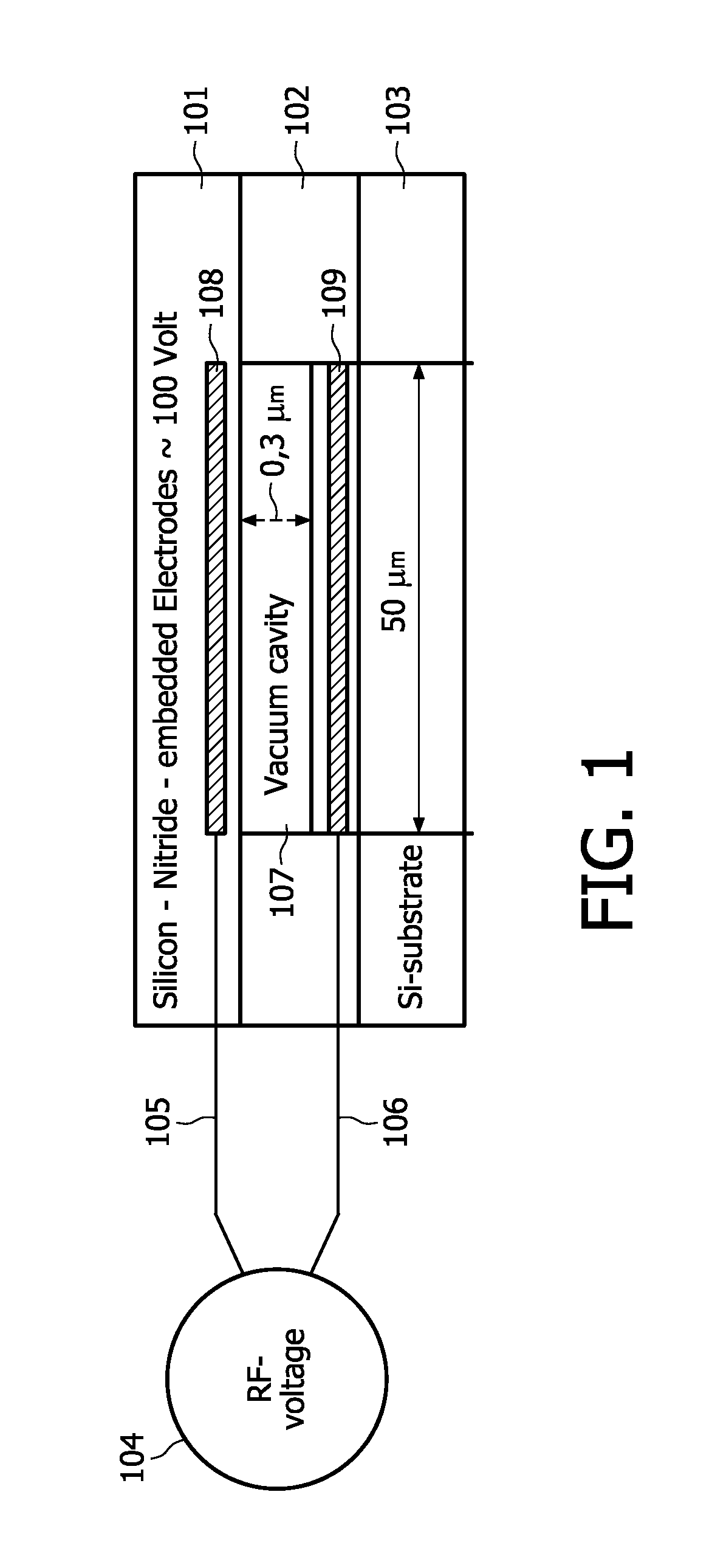
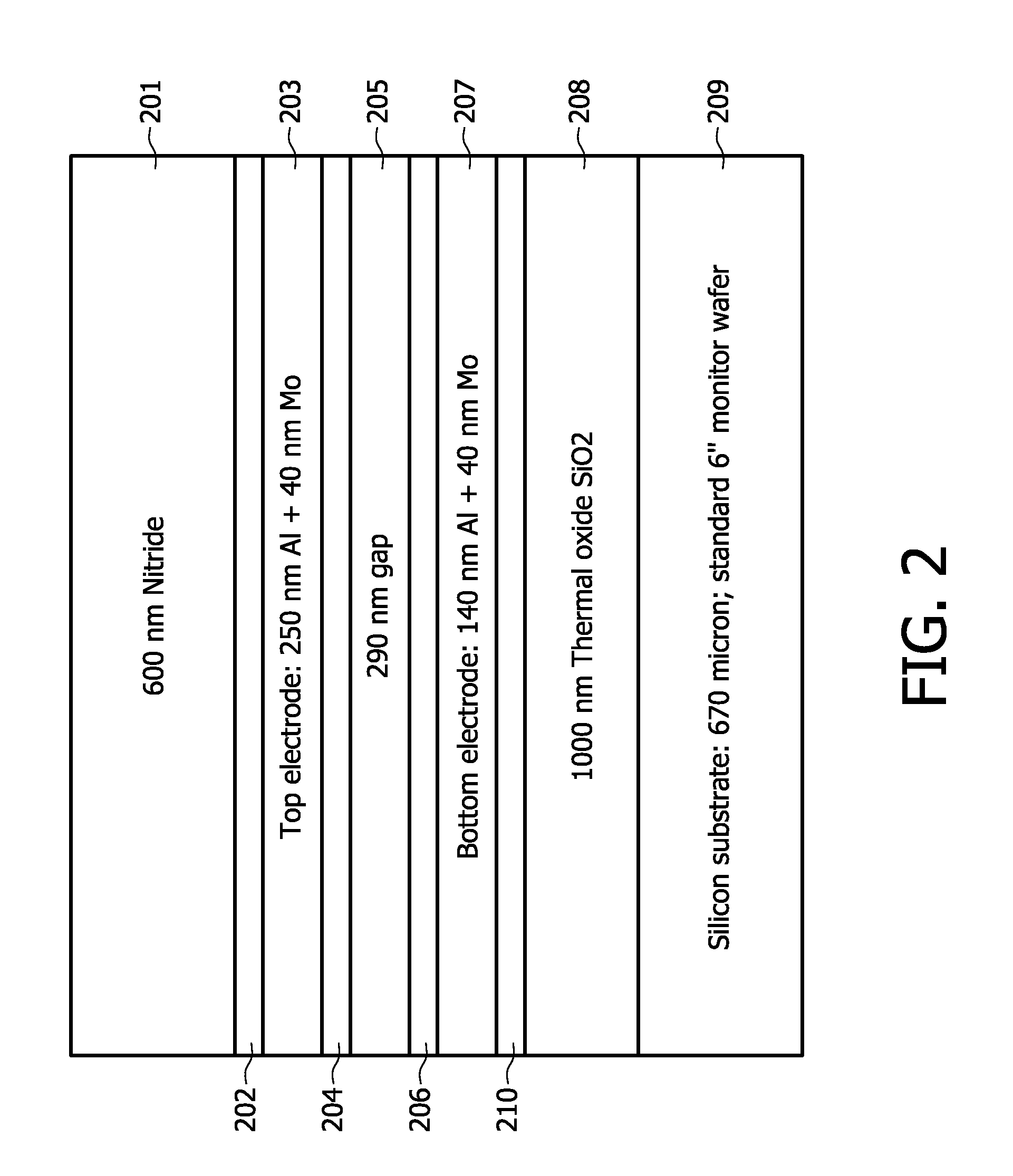
[0039]The transducer can be manufactured by a CMOS compatible processing, wherein low temperature is used. The process is carried out with low temperature, because CMOS compatibility requires temperatures below 400° C. Firstly, with the help of a sacrificial etch of Al or poly / XeF2 etch a vacuum cavity is created. Secondly, within a PECVD silicon nitride a membrane is manufactured by inserting aluminum for use as electrode. PECVD nitride dielectric layers are used, because they have a high dielectric constant ε˜7 and good mechanical properties (E˜250 MPa).

Controlling charging is key problem for good and stable capacitive micromachined ultrasound transducer operation. Charging means the trapping of carriers in the dielectric layer and a dramatic change of the associated electric field in the dielectric layer. As a result, the properties of a capacitive micormachined ultrasound transducer will change (electric fields will be strongly affected). This effects output pressure, which is v...


PUM

PropertyMeasurementUnit
Temperatureaaaaaaaaaa
Thicknessaaaaaaaaaa
Pressureaaaaaaaaaa

Abstract

The patent application discloses a capacitive micromachined ultrasound transducer, comprising a silicon substrate; a cavity; a first electrode, which is arranged between the silicon substrate and the cavity; wherein the first electrode is arranged under the cavity; a membrane, wherein the membrane is arranged above the cavity and opposite to the first electrode; a second electrode, wherein the second electrode is arranged above the cavity and opposite to the first electrode; wherein the second electrode is arranged in or close to the membrane, wherein the first electrode and the second electrode are adapted to be supplied by a voltage; and a first isolation layer, which is arranged between the first electrode and the second electrode, wherein the first isolation layer comprises a dielectric. It is also described a system for generating or detecting ultrasound waves, wherein the system comprises a transducer according to the patent application. Further, it is disclosed a method for manufacturing a transducer according to the patent application, wherein the transducer is manufactured with the help of a CMOS manufacturing process, wherein the transducer can be manufactured as a post-processing feature during a CMOS process.

Description

FIELD OF THE INVENTION[0001]The present invention relates to a capacitive micromachined ultrasound transducer, a system for generating or detecting ultrasound waves and a method for manufacturing a transducer.BACKGROUND OF THE INVENTION[0002]A capacitive micromachined ultrasound transducer (CMUT) is essentially a parallel plate capacitor. The top electrode is embedded in a membrane. An RF-voltage across the electrodes makes the membrane vibrate, typically at a few MHz. Capacitive micromachined ultrasound transducers are known for high efficiency and high output power.SUMMARY OF THE INVENTION[0003]However, charging is a known disadvantage of capacitive micromachined ultrasound transducers of the prior art and often prevents its practical implementation. Due to charging the transducer may be unstable and its characteristics may drift.[0004]Therefore, it is desirable to provide an improved transducer and method for solving the charging problem. The solution of the charging problem acco...

Claims


Application Information

Patent Timeline
IPC IPC(8): H02N1/00H04R31/00
CPCY10T29/49005B06B1/0292H02N1/006H02N1/08B60B1/0292
Inventor KLOOTWIJK, JOHAN H.DIRKSEN, PETERMULDER, MARCELMOONEN, ELISABETH M. L.
Owner KONINKLIJKE PHILIPS ELECTRONICS NV
Why Eureka
Try Eureka