Fresnel lens coating process

Inactive Publication Date: 2011-07-07
ESSILOR INT CIE GEN DOPTIQUE
View PDF10 Cites 16 Cited by
  • Summary
  • Abstract
  • Description
  • Claims
  • Application Information

AI Technical Summary

Benefits of technology

[0016]It has been discovered that it is possible to obtain a good optical surface quality with an acceptably smooth coated structured surface, that is reduced surface roughness, without excessively thick coatings of the order to 1 or 2 mm, by adapting the coating to the height of the structured surface or Fresnel surface of the Fresnel lens. Specifically, by adopting coating thickness

Problems solved by technology

By contrast when the incident UV radiation is directed at the glass mold, the shrinkage of the coating liquid develops from Fresnel structure surface, again in a direction opposite to t

Method used


Image

  • Fresnel lens coating process
  • Fresnel lens coating process
  • Fresnel lens coating process

Examples


Example

Example 1

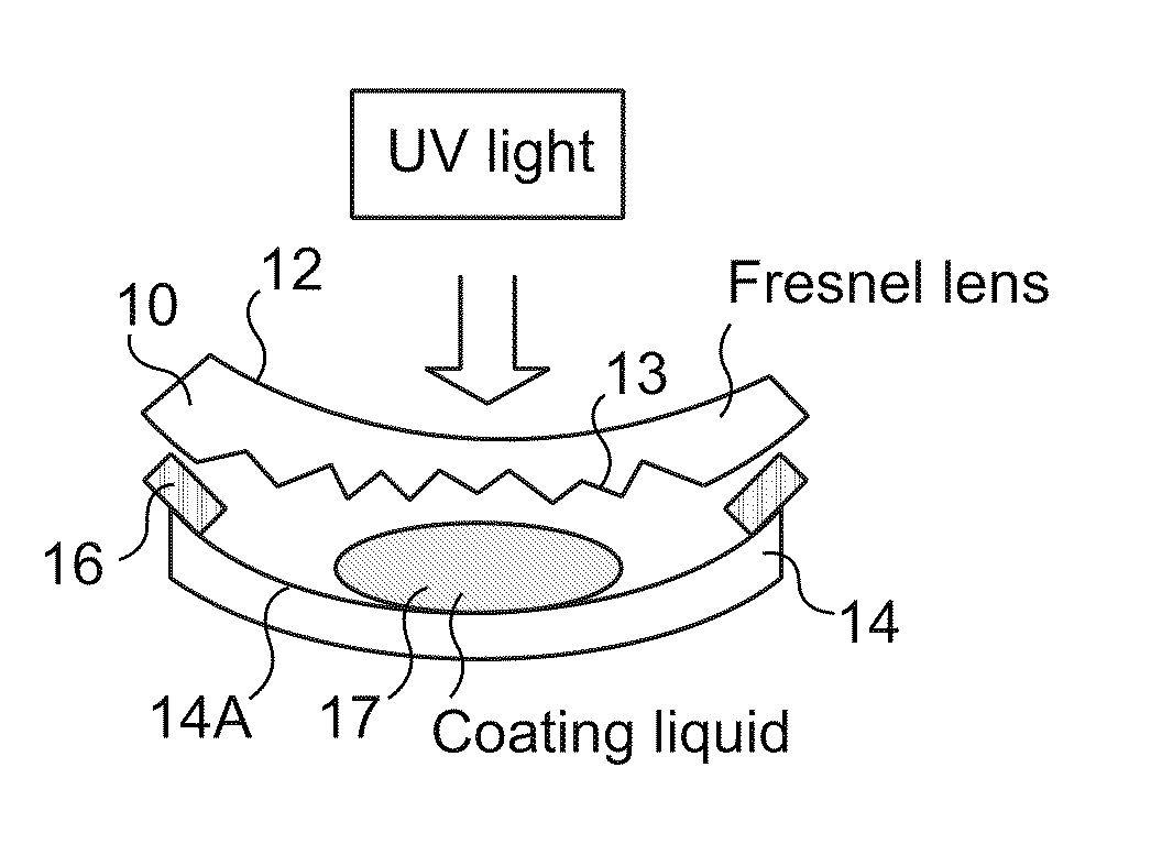
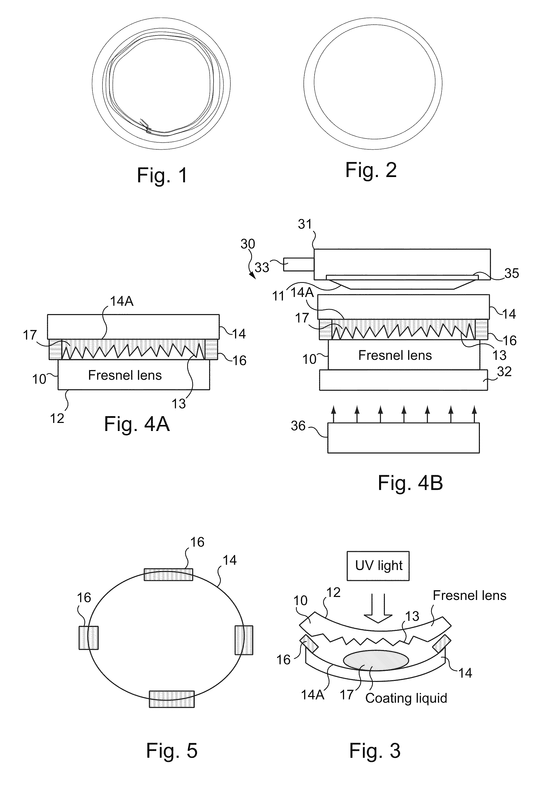
[0072]A 4.0 base Fresnel lens blank of polycarbonate having a refractive index of 1.59 was injection molded. In the present example the Fresnel structure or the structured surface of the Fresnel lens blank was located on the convex side of a convex-concave lens blank (see FIG. 3). The Fresnel structure height of the structured surface of the Fresnel lens blank was 150 μm and the optical power of the Fresnel lens design in air was +6.0.

[0073]A corresponding 4.0 base glass mold part had a molding surface which matches the base curvature of the Fresnel lens structured surface. So-called spacer tape was used for defining the plurality of spacers between the mold part and the Fresnel lens blank. The spacer tape portions were applied to the edge of the glass mold part at circumferentially spaced locations and also to the edge of the Fresnel lens blank and served to calibrate the thickness of the coating composition in association with the application of light pressure by the air ...

Example

Example 2

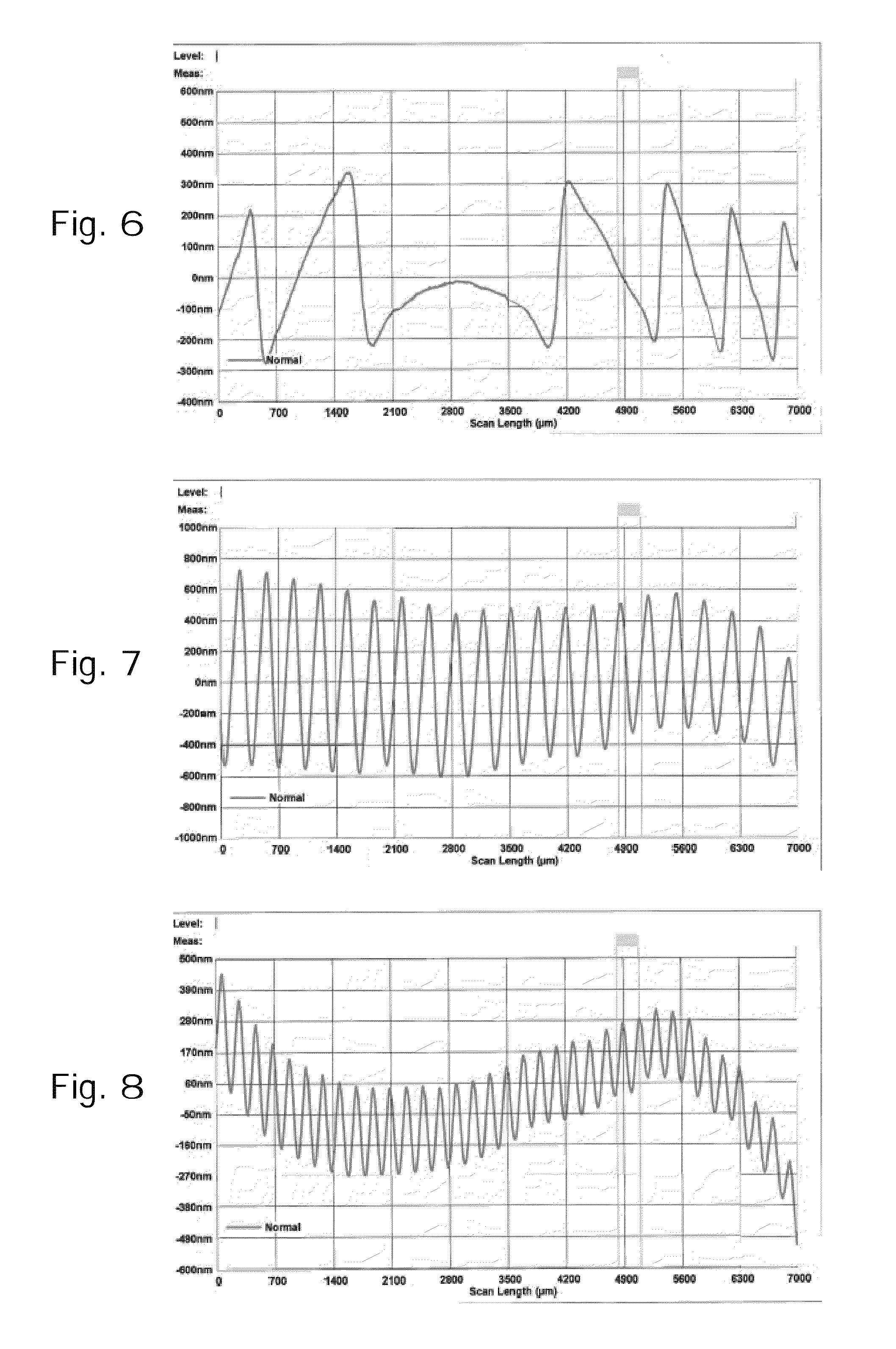
[0078]The modalities of this example were the same as those of Example 1, except as regards the axial length of the spacer tape portions which were approximately 650 μm to obtain a coating thickness of about 620 μm. The surface quality of the much thicker coating of Example 2 is even better than that of Example 1. The surface roughness was less than 100 nm and the optical quality was good, too.

Example

Example 3

[0079]The modalities of this example were the same as those of Example 1, except that the Fresnel lens bulk material was a high index polythiourethane (nD=1.60). The polythiourethane lens blank was of the same design as the polycarbonate Fresnel lens of Examples 1 and 2. The resulting coated Fresnel lens blank produced by the press coating process had the same good optical and cosmetic qualities as those of the coated lens blank of Example 1.


PUM


Abstract

The present method for coating a Fresnel lens blank includes providing an uncoated Fresnel lens blank having a structure surface and a non-structured surface, providing a transparent mold part having molding surface substantially matching the base curvature of the Fresnel lens, depositing a metered quantity of coating resin between the molding surface and the structured surface of the Fresnel lens, applying pressure between the Fresnel lens and the mold part while maintaining the distance between the molding surface and the structure surface so that the thickness of the coating is greater than 1.5 times the Fresnel structural height of the structured surface and less than 5 times of the Fresnel structure height of the structured surface and curing the resin coating in situ by directing the incident UV radiation at the Fresnel lens. A double coating may be employed for obtaining both higher optical power and better mechanical properties.

Description

CROSS REFERENCE TO RELATED APPLICATION[0001]This application is a continuation-in-part of co-pending application Ser. No. 12 / 651,646 filed on Jan. 4, 2010. The entire contents of the above-identified application is hereby incorporated by reference.FIELD OF THE INVENTION[0002]The present application relates to a process for coating Fresnel lenses, and in particular for coating Fresnel lenses for ophthalmic lens applications.BACKGROUND OF THE INVENTION[0003]There is an increasing interest in adopting Fresnel lenses which are diffractive lenses for certain ophthalmic applications in lieu of more conventional refractive lenses. Among the reasons for the increased interest in Fresnel lenses for ophthalmic applications is the increased lens optical power and / or reduced lens thickness.[0004]One problem which has slowed the industrial development of Fresnel lenses for ophthalmic applications is related to their fabrication. A Fresnel lens conventionally has a so-called structured surface or...

Claims


Application Information

Patent Timeline
IPC IPC(8): G02B3/08G02B1/10B05D3/02B05D3/06B05D1/38B05D3/00
CPCG02B3/08G02B1/10
Inventor JIANG, PEIQIWARREN, LOISWRIGHT, DANNEGOULET, ALAIN
Owner ESSILOR INT CIE GEN DOPTIQUE
Why Eureka
Try Eureka