
Cnt-infused fiber as a self shielding wire for enhanced power transmission line

Active Publication Date: 2011-07-21
APPL NANOSTRUCTURED SOLUTIONS LLC
View PDF102 Cites 64 Cited by
  • Summary
  • Abstract
  • Description
  • Claims
  • Application Information

AI Technical Summary

Benefits of technology

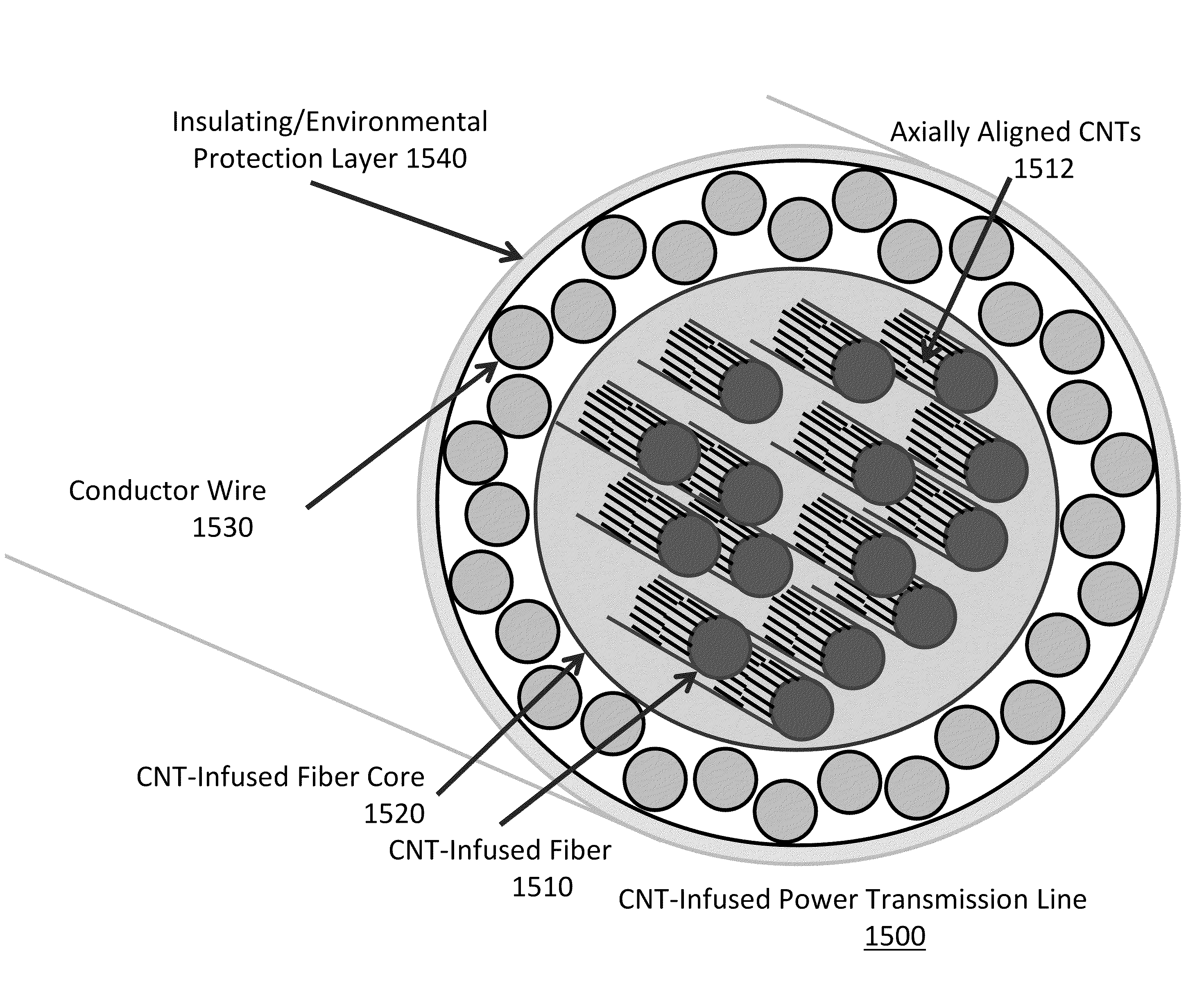
In a further aspect of the disclosure, a self-shielded wire or a wire sheathing is described that incorporates a built-in shielding capability that may improve overall product performance and reduce weight and cost. The electromagnetic shield for the wire may include a plurality of carbon nanotube infused fibers. The infused carbon nanotubes may be aligned radially about the fiber axes. The plurality of carbon nanotube infused fibers may be arranged circumferentially about the wire with the fiber axes parallel to the wire.
In yet another aspect of the disclosure, a power transmission cable is described that includes a high strength core that may aid in improving power transmission capability to improve overall product performance, reduce weight, and cost.

Problems solved by technology

A significant issue in the power transmission industry is cost associated with transmission / distribution loss (up to 6.5% in 2007) as well as the infrastructure cost associated with suspending power lines whose spans are limited by the strength / stifthess of the line itself.
Over time lines begin to sag requiring maintenance.
In addition, power transmission and data transfer lines suffer from signal distortion due in part to crosstalk, stray inductance or capacitance created by other lines, and noise, interference created by external sources.
While these techniques have been shown to reduce issues related to crosstalk and noise, the these techniques can add significant weight and cost to components utilizing twisted pairs or shielded wire.

Method used


Image

  • Cnt-infused fiber as a self shielding wire for enhanced power transmission line
  • Cnt-infused fiber as a self shielding wire for enhanced power transmission line
  • Cnt-infused fiber as a self shielding wire for enhanced power transmission line

Examples


example i

This example shows how a fiber material can be infused with CNTs in a continuous process to target thermal and electrical conductivity improvements.

In this example, the maximum loading of CNTs on fibers is targeted. 34-700 12 k carbon fiber tow with a tex value of 800 (Grafil Inc., Sacramento, Calif.) is implemented as the carbon fiber substrate. The individual filaments in this carbon fiber tow have a diameter of approximately 7 μm.

FIG. 8 depicts system 800 for producing CNT-infused fiber in accordance with the illustrative aspect of the present disclosure. System 800 includes a carbon fiber material payout and tensioner station 805, sizing removal and fiber spreader station 810, plasma treatment station 815, barrier coating application station 820, air dry station 825, catalyst application station 830, solvent flash-off station 835, CNT-infusion station 840, fiber bundler station 845, and carbon fiber material uptake bobbin 850, interrelated as shown.

Payout and tension station 805...

example ii

This example shows how fiber material can be infused with CNTs in a continuous process to target improvements in mechanical properties, especially interfacial characteristics such as shear strength. In this case, loading of shorter CNTs on fibers is targeted. In this example, 34-700 12 k unsized carbon fiber tow with a tex value of 793 (Grafil Inc., Sacramento, Calif.) is implemented as the carbon fiber substrate. The individual filaments in this carbon fiber tow have a diameter of approximately 7 μm.

FIG. 9 depicts system 900 for producing CNT-infused fiber in accordance with the illustrative aspect of the present disclosure, and involves many of the same stations and processes described in system 800. System 900 includes a carbon fiber material payout and tensioner station 902, fiber spreader station 908, plasma treatment station 910, catalyst application station 912, solvent flash-off station 914, a second catalyst application station 916, a second solvent flash-off station 918, b...

example iii

This example shows how fiber material can be infused with CNTs in a continuous process to target improvements in mechanical properties, especially interfacial characteristics such as interlaminar shear.

In this example, loading of shorter CNTs on fibers is targeted. In this example, 34-700 12 k unsized carbon fiber tow with a tex value of 793 (Grafil Inc., Sacramento, Calif.) is implemented as the carbon fiber substrate. The individual filaments in this carbon fiber tow have a diameter of approximately 7 μm.

FIG. 10 depicts system 1000 for producing CNT-infused fiber in accordance with the illustrative aspect of the present disclosure, and involves many of the same stations and processes described in system 800. System 1000 includes a carbon fiber material payout and tensioner station 1002, fiber spreader station 1008, plasma treatment station 1010, coating application station 1012, air dry station 1014, a second coating application station 1016, a second air dry station 1018, CNT-inf...


PUM

PropertyMeasurementUnit
Lengthaaaaaaaaaa
Percent by massaaaaaaaaaa

Abstract

A wire includes a plurality of carbon nanotube infused fibers in which the infused carbon nanotubes are aligned parallel to the fiber axes. An electromagnetic shield for a wire includes a plurality of carbon nanotube infused fibers, in which the infused carbon nanotubes are aligned radially about the fiber axes. The plurality of carbon nanotube infused fibers are arranged circumferentially about the wire with the fiber axes parallel to the wire. A self-shielded wire includes 1) a wire that includes a plurality of carbon nanotube infused fibers in which the infused carbon nanotubes are aligned parallel to the fiber axes; and 2) an electromagnetic shield that includes a plurality of carbon nanotube infused fibers in which the carbon nanotubes are aligned radially about the fiber axes. The axes of the carbon nanotube infused fibers of the wire and the carbon nanotube infused fibers of the electromagnetic shield share are parallel.

Description

FIELDAn aspect of the present disclosure may relate to the field of power transmission, and more particularly, to a carbon nanotube (CNT) infused fiber as a self shielding wire for enhanced power transmission.BACKGROUNDThere are over 300,000 km of power transmission lines traversing the USA (and many km more across the world) delivering electrical power through aluminum conductors with various forms of additional reinforcement. A significant issue in the power transmission industry is cost associated with transmission / distribution loss (up to 6.5% in 2007) as well as the infrastructure cost associated with suspending power lines whose spans are limited by the strength / stifthess of the line itself. Over time lines begin to sag requiring maintenance.In addition, power transmission and data transfer lines suffer from signal distortion due in part to crosstalk, stray inductance or capacitance created by other lines, and noise, interference created by external sources. Signal distortion ...

Claims


Application Information

Patent Timeline
IPC IPC(8): H01B7/00B29C35/02B82Y40/00B82Y99/00
CPCH05K9/009H01B3/004B32B9/00B32B27/06B82B1/00C07C53/00
Inventor SHAH, TUSHAR K.ADCOCK, DANIEL J.MALECKI, HARRY C.
Owner APPL NANOSTRUCTURED SOLUTIONS LLC
Learn More