Intermediate transfer belt, method for producing the same, and image forming apparatus

a transfer belt and transfer method technology, applied in the direction of electrographic process equipment, printing, instruments, etc., can solve the problems of inability to achieve accurate registration, slow printing speed, and out-of-color registration, and achieve the effect of high transferability and high durability

Active Publication Date: 2011-07-21
RICOH KK
View PDF7 Cites 20 Cited by
  • Summary
  • Abstract
  • Description
  • Claims
  • Application Information

AI Technical Summary

Benefits of technology

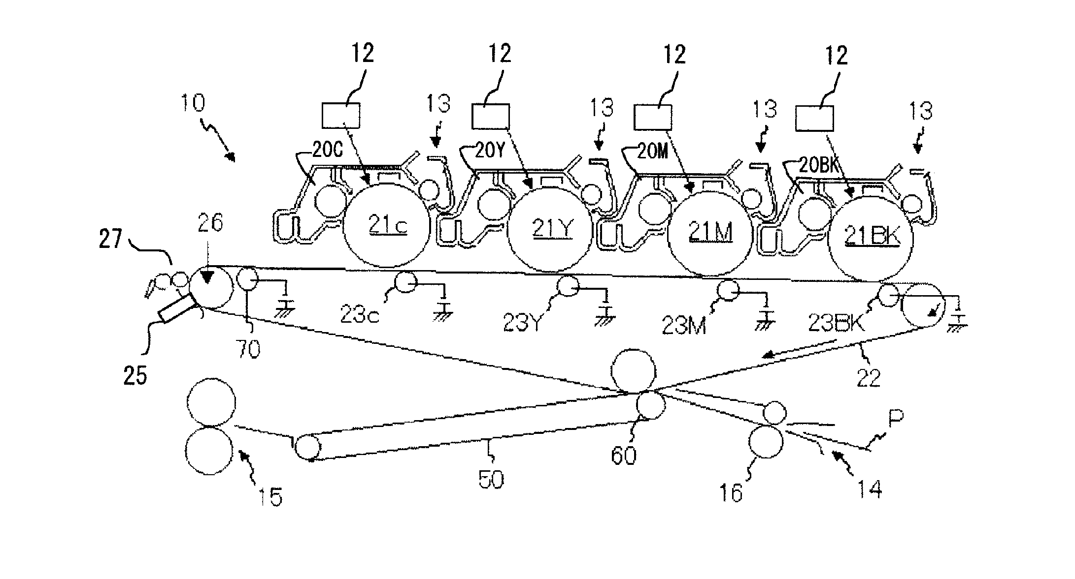
[0039]The present invention can provide an intermediate transfer belt which can realize a high transferability regardless of the type (surface conditions) of the recording medium for a long period of time, which does not damage organic photoconductors, and which can form highly durable, high-quality images for a long period of time; a method for producing the intermediate transfer belt; and an image forming apparatus containing the intermediate transfer belt.

Problems solved by technology

In such intermediate transfer belt system, with respect to a photoconductor four developing units are used, but use of such intermediate transfer belt system has a disadvantage that print speed is slow.
However, in this system, it is difficult to achieve accurate registration upon superimposing respective images because of change of paper condition due to environment, causing out-of-color registration.
For this reason, characteristics required for the intermediate transfer belt have been tough to achieve, such as high speed transfer, positional accuracy, etc., but it is necessary to satisfy those characteristics.
Also, such an intermediate transfer belt has poor followability to a photoconductor, paper, etc., which are brought into contact with the intermediate transfer belt at transfer positions.
Such poor followability may cause insufficient contact portions (spaces) at the transfer positions, leading to uneven transfer.
Poor followability causes unevenness in image density and color toner following irregularities of paper.
In addition, although the followability to irregularities of paper is improved, toner cannot be separated from the surface layer since the toner releasability of the surface is poor.
Furthermore, such a surface layer is problematically degraded in wear resistance and abrasion resistance.
The protective layer made of a material having sufficiently high transferability cannot comply with the flexible layer and is unfavorably cracked or peeled off.
However, in the technique disclosed in this patent literature, the particles tend to be exfoliated.
Thus, this technique is not sufficient to meet the requirements for the recent electrophotographic apparatuses.
However, the particle layer is thick and has ununiform areas formed due to aggregation of the particles, causing variation in transferability.
This technique is not sufficient to meet the requirements for the formation of high-quality images by the recent electrophotographic apparatuses.
However, even in these proposals, the particles are stacked in the thickness direction, and some of the particles are completely embedded in the resin layer, resulting in that the particles are ununiformly present in the layer.
This technique is also not sufficient to meet the requirements for the formation of high-quality images by the recent electrophotographic apparatuses.
Furthermore, such inorganic particles as silica tend to scratch and abrade the surface of an organic photoconductor, which is suitably used as an image bearing member responsible for image formation, when comes into contact with the organic photoconductor at the transfer position, causing a failure of degrading durability.

Method used


Image

  • Intermediate transfer belt, method for producing the same, and image forming apparatus
  • Intermediate transfer belt, method for producing the same, and image forming apparatus
  • Intermediate transfer belt, method for producing the same, and image forming apparatus

Examples


example 1

[0205]A base layer-coating liquid was prepared as follows, and was used to produce a base layer of a seamless belt.

[0206]First, carbon black (SPECIAL BLACK 4, product of Evonik Degussa) was dispersed in N-methyl-2-pyrrolidone with a bead mill. The resultant dispersion liquid was added to polyimide varnish mainly containing a polyimide resin precursor (U-VARNISH A, product of UBE INDUSTRIES, LTD.) so that the carbon black content was adjusted to 17% by mass of the solid content of polyamic acid, followed by thoroughly stirring and mixing, to thereby prepare a coating liquid.

[Production of Seamless Belt]

[0207]Next, a metal cylinder (outer diameter: 100 mm, length: 300 mm) was subjected to blast treatment so as to have a rough surface, and then used as a mold. While the resultant cylindrical mold was being rotated at 50 rpm, the above base layer-coating liquid was uniformly flow-cast onto the outer surface of the cylindrical mold using a dispenser. At the point when all of a predetermi...

example 2

[0216]The procedure of Example 1 was repeated, except that the spherical resin particles were changed to silicone resin particles (X-52-854, volume average particle diameter: 0.8 μm, product of Shin-Etsu Chemical Co., Ltd.), to thereby produce intermediate transfer belt B.

[0217]From an electron microscopic cross-sectional image of the produced belt, the embedment rate of the particles in the resin layer was found to be 53%.

example 3

[0218]The procedure of Example 1 was repeated, except that the spherical resin particles were changed to silicone resin particles (TOSPEARL 120, volume average particle diameter: 2.0 μm, product of Momentive Performance Materials Inc.), to thereby produce intermediate transfer belt C.

[0219]From an electron microscopic cross-sectional image of the produced belt, the embedment rate of the particles in the resin layer was found to be 75%.


PUM


Abstract

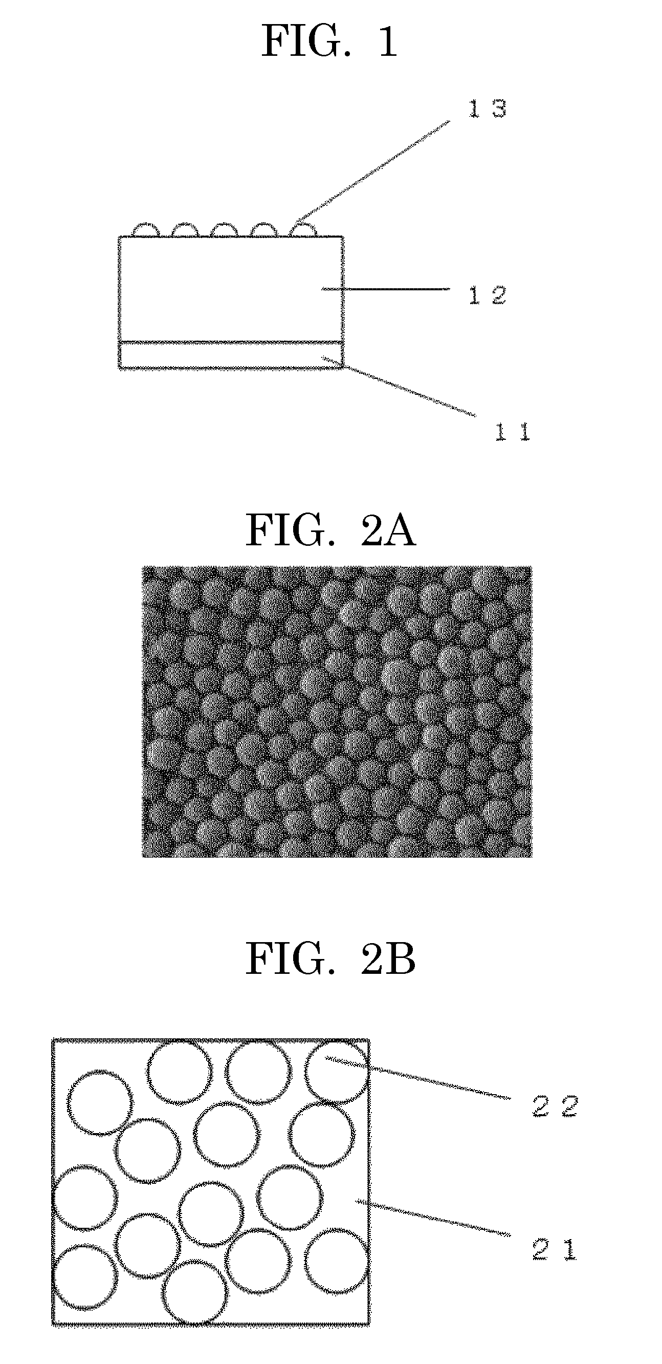
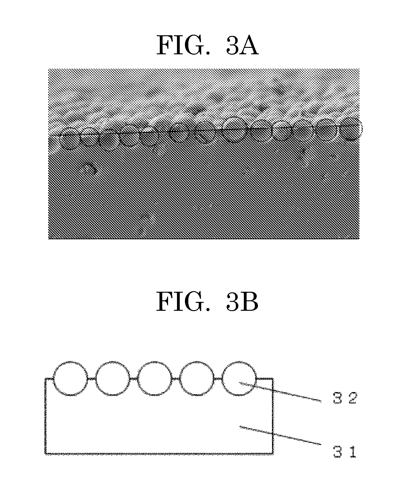
An intermediate transfer belt including a resin layer, which is a surface layer of the intermediate transfer belt, wherein the resin layer has a concavo-convex pattern formed by spherical resin particles which are independently embedded in the resin layer so that the embedment rate of the spherical resin particles in the thickness direction of the resin layer is higher than 50% but lower than 100%.

Description

BACKGROUND OF THE INVENTION[0001]1. Field of the Invention[0002]The present invention relates to an intermediate transfer belt (seamless belt) which is mounted in image forming apparatuses such as copiers, printers or the like, and is suitable for full-color image formation, a method for producing the intermediate transfer belt, and an electrophotographic apparatus using the intermediate transfer belt.[0003]2. Description of the Related Art[0004]Conventionally, in electrophotographic image forming apparatuses, seamless belts have been used as members for various applications. Particularly, in full-color electrophotographic apparatuses of recent years, an intermediate transfer belt system is used, in which development images of four colors: yellow, magenta, cyan, black, are superimposed on an intermediate transfer medium, and then the superimposed images are collectively transferred to a transfer medium, such as paper.[0005]In such intermediate transfer belt system, with respect to a...

Claims


Application Information

Patent Timeline
Patent Type & Authority Applications(United States)
IPC IPC(8): B41M3/12G03G15/01
CPCG03G15/1605G03G15/162G03G15/14G03G15/16
Inventor AOTO, JUNKUBO, HIDETAKAMASHIKO, KENICHIKATOH, SAYAKANITTA, SHINICHIOONUMA, SHIGEO
Owner RICOH KK
Why Eureka
Try Eureka