Extremely high liquid barrier fabrics

a technology of liquid barrier fabric and fabric, applied in the field of nonwoven fibrous structure, can solve the problems of life-threatening heat stress, clothing limitations impose limitations on activity, and higher air flow resistan

Active Publication Date: 2011-07-21
DUPONT SAFETY & CONSTR INC
View PDF28 Cites 15 Cited by
  • Summary
  • Abstract
  • Description
  • Claims
  • Application Information

AI Technical Summary

Benefits of technology

[0005]Physical activity flexes fabric and garment. If a fabric has low enough resistance to air flow, this, in turn, produces a pumping action which pushes and pulls air back and forth through the fabric. By this mechanism, the exchange of warm moisture laden air within the garment with ambient air provides a significant cooling effect. Tests of protective garments made of the same cut, but with widely differing air flow resistance under warm humid conditions (32° C., 60% RH), have shown that the garments made of fabrics with the least air flow resistance repeatedly allowed subjects to achieve higher levels of activity without incurring heat stress. Conversely, garments made of fabrics with the highest air flow resistance limited the physical activity of the same subjects to the lowest levels to avoid heat stress. Garments made of fabrics having intermediate air flow resistance allowed subjects to achieve intermediate levels of activity without heat stress. The intermediate activity levels correlated very well with the air flow resistance of the fabric.
[0007]Clothing provides protection from hazards in the environment. The degree of protection clothing imparts is dependent upon the effectiveness of the barrier characteristics of the clothing. Where the function of the barrier is to keep environmental particulates or fluids from penetrating a garment to reach the wearer, barrier is easily correlated with fabric pore size. The most effective barriers generally have the smallest pore size.

Problems solved by technology

Clothing which appreciably inhibits heat transfer can cause heat and moisture buildup and this can result in discomfort due to warm, sticky, clammy and or sweaty sensations.
In the extreme case, for example, where protective clothing prevents adequate thermal regulation during activity in a warm and humid environment, such clothing limitations not only lead to discomfort, but can result in life-threatening heat stress.
For this reason, frequently, clothing limitations impose limitations on activity to avoid the consequences of heat stress.
Conversely, garments made of fabrics with the highest air flow resistance limited the physical activity of the same subjects to the lowest levels to avoid heat stress.
Unfortunately, smaller pore size also generally results in higher air flow resistance.
Microporous films have been used in barrier materials to achieve extremely high hydrostatic head liquid barrier properties, but at the expense of breathability, such that their Frazier permeabilities are unacceptably low, rendering fabrics containing such films uncomfortable for the wearer.
However, production of such small fibers has presented many problems including low throughput, poor efficiency in spinning and difficulties in fiber collection.

Method used


Image

  • Extremely high liquid barrier fabrics
  • Extremely high liquid barrier fabrics
  • Extremely high liquid barrier fabrics

Examples


examples

[0066]Sample fabrics were made by dissolving various polymers in suitable solvents which were then fed into an electrospinning apparatus, such as that described in U.S. Pat. No. 4,127,706, incorporated herein by reference. The fine fibers formed were deposited onto a melt blown fabric support layer to form a barrier layer of the fine fibers, and mechanical strength was imparted to the samples by sandwiching the fine fiber / melt blown layers between layers of spunbond polyester fibers, to form a four-layer laminate of spunbond / melt blown / fine fiber / spunbond configuration.

[0067]Fine fibers were spun from two different hydrophobic polymers: Kraton™ D1134x, a styrene-butadiene copolymer (specific gravity=0.94), available from Kraton™ Polymers of Houston, Tex.; and Kynar™ 761, a polyvinylidene fluoride polymer (specific gravity=1.76), available from Atofina Chemicals, Inc. of Philadelphia, Pa. Kraton™ fine fibers were spun from solutions of 9 wt. % polymer in a mixed solvent of 88 / 12 wt %...

examples 1-9

[0077]Kraton™ D1133x copolymer was dissolved in a mixed solvent of 88 wt. % tetrahydrofuran / 12 wt. % dimethyl acetamide at a polymer concentration of 9 wt. %, and electrospun at −18 KV at a rate of 0.5 ml / hr. Fine fibers were deposited onto samples of 18 g / m2 bicomponent melt blown fabric described in the Control Examples at a collection distance of approximately 22 cm. The fine fiber layer was then covered with a layer of spunbonded polyester, removed from the sample target. The layer of melt blown collection fabric was also covered with a layer of spunbonded polyester and all four layers were consolidated into a laminate. The barrier properties of the Examples were measured and are reported below in Table 4.

[0078]The fine fibers collected were measured by scanning electron microscopy and found to have diameters in a general range of between about 0.1 to 1.8 micrometers, with the average fiber diameters believed to be less than about 1 micrometer.

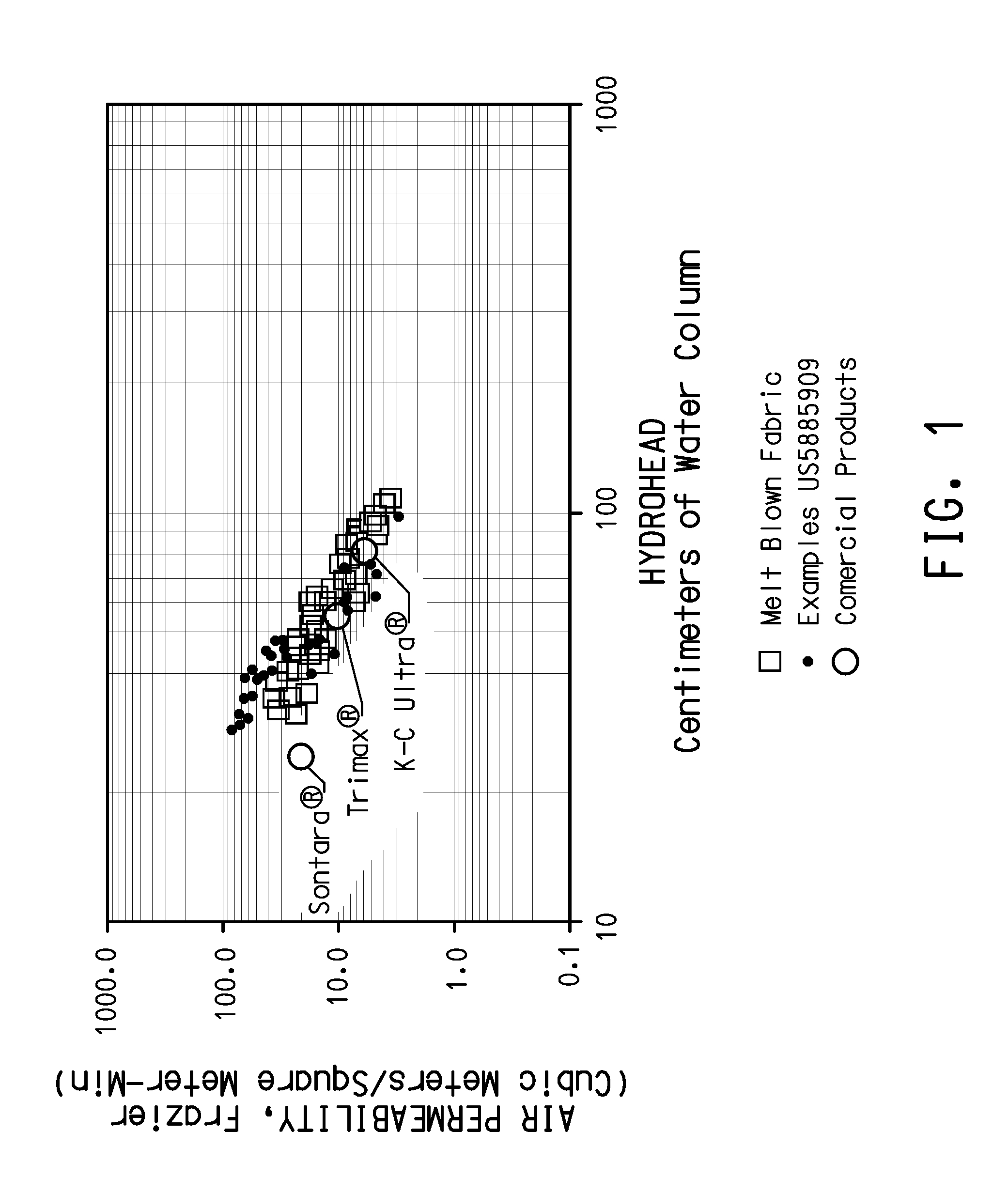
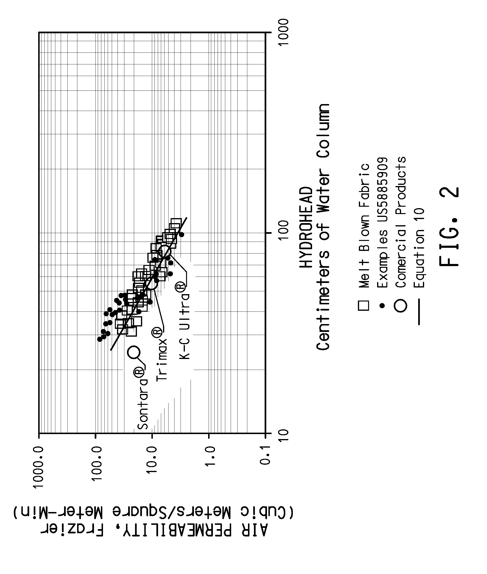
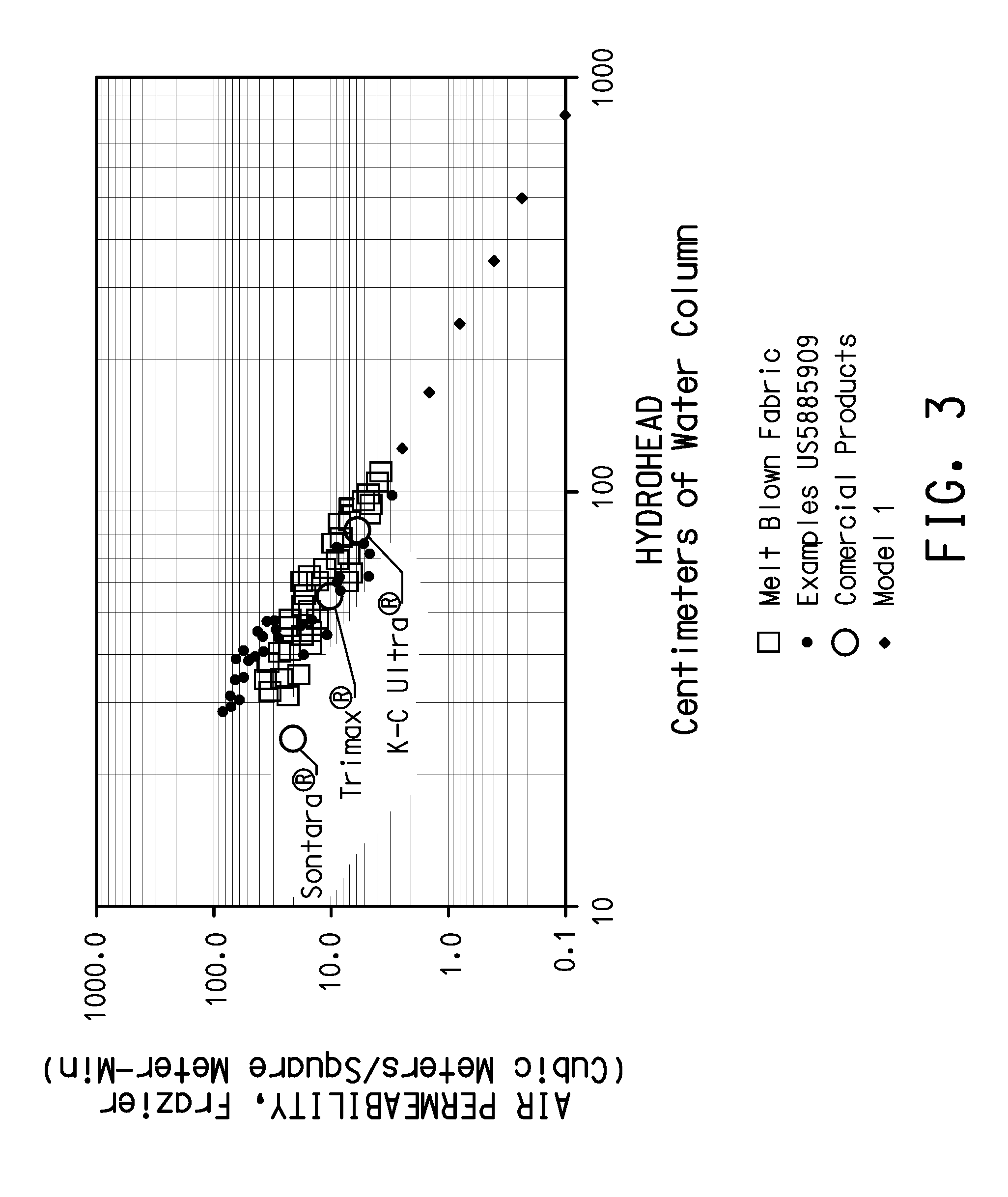
TABLE 4Fiber loadFrazierHydroheadBu...

examples 10-19

[0080]Kynar™ polymer was dissolved in acetone solvent at a polymer concentration of 15 wt. %, and electrospun at −20 KV at a rate of 5 ml / hr. Fine fibers were deposited onto samples of 18 g / m2 bicomponent melt blown fabric described in the Control Examples at a collection distances of approximately 22-30 cm. The fine fiber layer was then covered with a layer of spunbonded polyester, removed from the sample target. The layer of melt blown collection fabric was also covered with a layer of spunbonded polyester and all four layers were consolidated into a laminate. The barrier properties of the Examples were measured and are reported below in Table 5.

[0081]The fine fibers collected were measured by scanning electron microscopy and found to have diameters in a general range of between about 0.14 to 2.8 micrometers, with the average fiber diameters believed to be less than about 1 micrometer.

TABLE 5Fiber loadFrazierHydroheadBubblepointExample #(g / m2)(m3 / m2-min)(cmwc)(micrometers)1013.611...


PUM

PropertyMeasurementUnit
diametersaaaaaaaaaa
diametersaaaaaaaaaa
diametersaaaaaaaaaa

Abstract

One embodiment of the present invention is a nonwoven fabric comprising a support web and a fibrous barrier web, having a hydrohead of at least about 145 cm and a Frazier permeability of at least about 0.3 m3 / m2-min.

Description

[0001]This invention relates to nonwoven fibrous structures and more particularly to breathable fabrics and sheet structures formed by fibers which are held together without weaving or knitting.[0002]Nonwoven fibrous structures have existed for many years and today there are a number of different nonwoven technologies in commercial use. To illustrate the breadth of nonwoven technologies, paper is probably one of the earliest developed nonwoven fibrous structures. Nonwoven technologies continue to be developed by those seeking new applications and competitive advantages. One broad market area that has proven to be highly desirable because of its large volume and economics is the protective apparel market. This market comprises protection from hazardous chemicals such as in chemical spill clean up, from liquids such as blood in the medical field and from dry particulates or other hazards such as painting or asbestos removal.[0003]It is known that for a garment to be comfortable, it mu...

Claims


Application Information

Patent Timeline
Patent Type & Authority Applications(United States)
IPC IPC(8): B32B5/26A61F13/15D04H3/16D04H13/00
CPCA41D31/02A61F13/51462D04H13/007D04H13/002B32B5/26A41D31/102D04H1/559D04H1/56Y10T442/2164Y10T442/2189Y10T442/60Y10T442/608Y10T442/614Y10T442/621Y10T442/626Y10T442/659Y10T442/66Y10T442/68Y10T442/681D04H3/007D04H3/016D06M7/00B32B5/022B32B2255/02B32B2255/26B32B2307/724B32B2307/73
Inventor BRYNER, MICHAEL ALLEN
Owner DUPONT SAFETY & CONSTR INC
Why Eureka
Try Eureka