[0059]For example, in case where the light having passed through the light-
reflective layer 16b (that reflects the right circularly-polarized light having a wavelength of λ16 is reflected but transmits the left circularly-polarized light having the same wavelength) next passes not through 16b but through 14a or 14b of which the
selective reflection center wavelength is not λ16, then the left circularly-polarized light component at the wavelength λ16 is to pass through the cholesteric liquid-crystal layer having a different
helical pitch size. In this case, the left circularly-polarized light at the wavelength λ16 is affected though slightly by the
optical rotation of the cholesteric liquid-crystal phase in the other light-reflective layers, thereby bringing about a change that the wavelength of the left circularly-polarized light component may be shifted. Naturally, this phenomenon is not limited to only the “left circularly-polarized light component at the wavelength λ16”, but is a change that occurs when a circularly-polarized light at a certain wavelength passes through a cholesteric liquid-crystal phase having a different
helical pitch. Though based on experimental data, the present inventors' assiduous studies have revealed that, when one circularly-polarized light component not reflected by a cholesteric liquid-crystal layer having a predetermined
helical pitch passes, while kept not reflected, through another cholesteric liquid-crystal layer having a different helical pitch, and when the number of the layers through which the light passes is 3 or more, then the negative influence on the circularly-polarized light component passing through the layers becomes remarkable, and after that, even when the circularly-polarized light could reach a cholesteric liquid-crystal layer capable of reflecting the light, the light
reflectivity of the layer remarkably lowers. In the invention, even when one pair of light-reflective layers of which the
selective reflection center wavelength is the same but which differ in the helical direction are not arranged to be neighbor to each other, the effect of the invention can be attained; however, the number of the other light-reflective layers (light-reflective layers as formed by individually fixing a cholesteric liquid-crystal layer that differs in the helical pitch and has a different
selective reflection center wavelength) to be arranged between the pair of light-reflective layers is preferably at most 2. Needless-to-say, preferably, the pair of light-reflective layers are directly neighbor to each other.
[0060]The light-reflective layers may be formed in various methods. One example is a
coating method to be described below. More concretely, a curable
liquid crystal composition capable of forming a cholesteric liquid-crystal layer is applied onto the surface of a substrate, an alignment layer or a light-
reflective layer or the like to form a cholesteric liquid-crystal phase of the composition, and then this is cured (for example, through
polymerization, crosslinking reaction or the like) to form the intended light-
reflective layer.
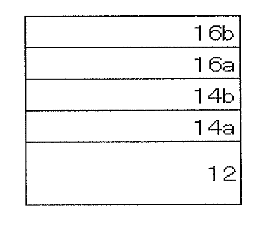
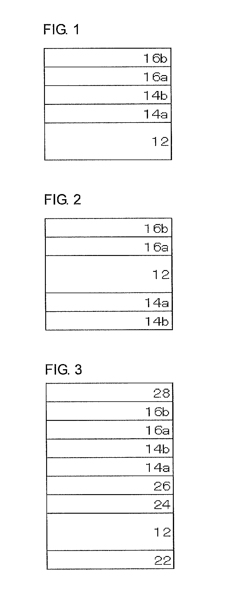
[0061]FIG. 2 shows a cross-sectional view of another embodiment of the infrared light reflecting plate of the invention. The infrared light reflecting plate 10′ shown in FIG. 2 has light-reflective layers 14a and 14b as formed on one surface of the substrate 12, and light-reflective layers 16a and 16b as formed on the other surface thereof. As in this, light-reflective layers may be laminated on both surfaces of the substrate 12. Preferably, however, the combination of light-reflective layers having the same reflection center wavelength is on the same surface side of the substrate 12.
[0062]The embodiment of the cholesteric liquid-crystal layers constituting the infrared light reflecting plate of the invention is not limited to those of FIG. 1 and FIG. 2. In other embodiments, five or more light-reflective layers may be laminated on one surface of the substrate, or one or more pairs of light-reflective layers may be formed on both surfaces of the substrate (therefore at least 5 layers in total). In still another embodiment, two or more pairs of light-reflective layers each having the same reflection center wavelength may be formed on one substrate.
[0063]Needless-to-say, the infrared light reflecting plate of the invention may be combined with any other infrared light reflecting plate for the purpose of further broadening the reflection
wavelength range. In addition, the reflector may have a light-reflective layer capable of reflecting a light having a predetermined wavelength on the basis of any other principle than the selective reflectivity characteristic of cholesteric liquid-crystal phase. Regarding the members capable of being combined with the reflector of the invention, there may be mentioned composite films and the layers constituting the films described in JP-T 4-504555, as well as multilayer laminates described in JP-T 2008-545556, etc.
[0064]Needless-to-say, the infrared light reflecting plate of the invention may have any other selective reflectivity characteristic for other
infrared wavelength regions (for example, from 780 to 940 nm, from 1400 to 2500 nm) than the above-mentioned two spectral peaks. For example, one additional pair of light-reflective layers each formed of a fixed cholesteric liquid-crystal phase, especially those formed of a fixed cholesteric liquid-crystal phase having a different
optical rotation (that is, having right or left
optical rotation) may be further laminated to thereby more broaden the selective reflection
wavelength range and to more enhance the heat-shielding capability of the reflector.

