
Wireless charging system for vehicle

a charging system and vehicle technology, applied in the direction of charging stations, electric vehicle charging technology, transportation and packaging, etc., to achieve the effect of convenient charging operation, simplified system, and light weight of the vehicle body

Inactive Publication Date: 2011-08-04
YAZAKI CORP
View PDF8 Cites 45 Cited by
  • Summary
  • Abstract
  • Description
  • Claims
  • Application Information

AI Technical Summary

Benefits of technology

According to the wireless charging system for a vehicle according to the invention, the AC power outputted from the electric power output section is amplified and further the AC power thus amplified is transmitted to the vehicle side by using the resonant power transmission method to thereby charge the battery. Thus, since the battery can be charged without coupling the feeding apparatus and the vehicle via a plug etc., the charging operation can be performed easily.
Further, since the control signal to be transmitted from the feeding apparatus to the vehicle can be superimposed on the AC power and transmitted, the control signal can be transmitted between the feeding apparatus and the vehicle. Thus, since the communication can be performed between the feeding apparatus and the vehicle without separately providing a communication apparatus, the system can be miniaturized and simplified, which contributes to the light-weighting of the weight of the vehicle body.

Problems solved by technology

Further, according to such the charging system, it is necessary to transmit and receive, between a feeding side apparatus and the vehicle, various kinds of control signals representing information of the remaining capacity of the battery, possible / impossible as to the charging, emergency stop due to the occurrence of abnormality, for example.

Method used


Image

  • Wireless charging system for vehicle
  • Wireless charging system for vehicle
  • Wireless charging system for vehicle

Examples


first embodiment

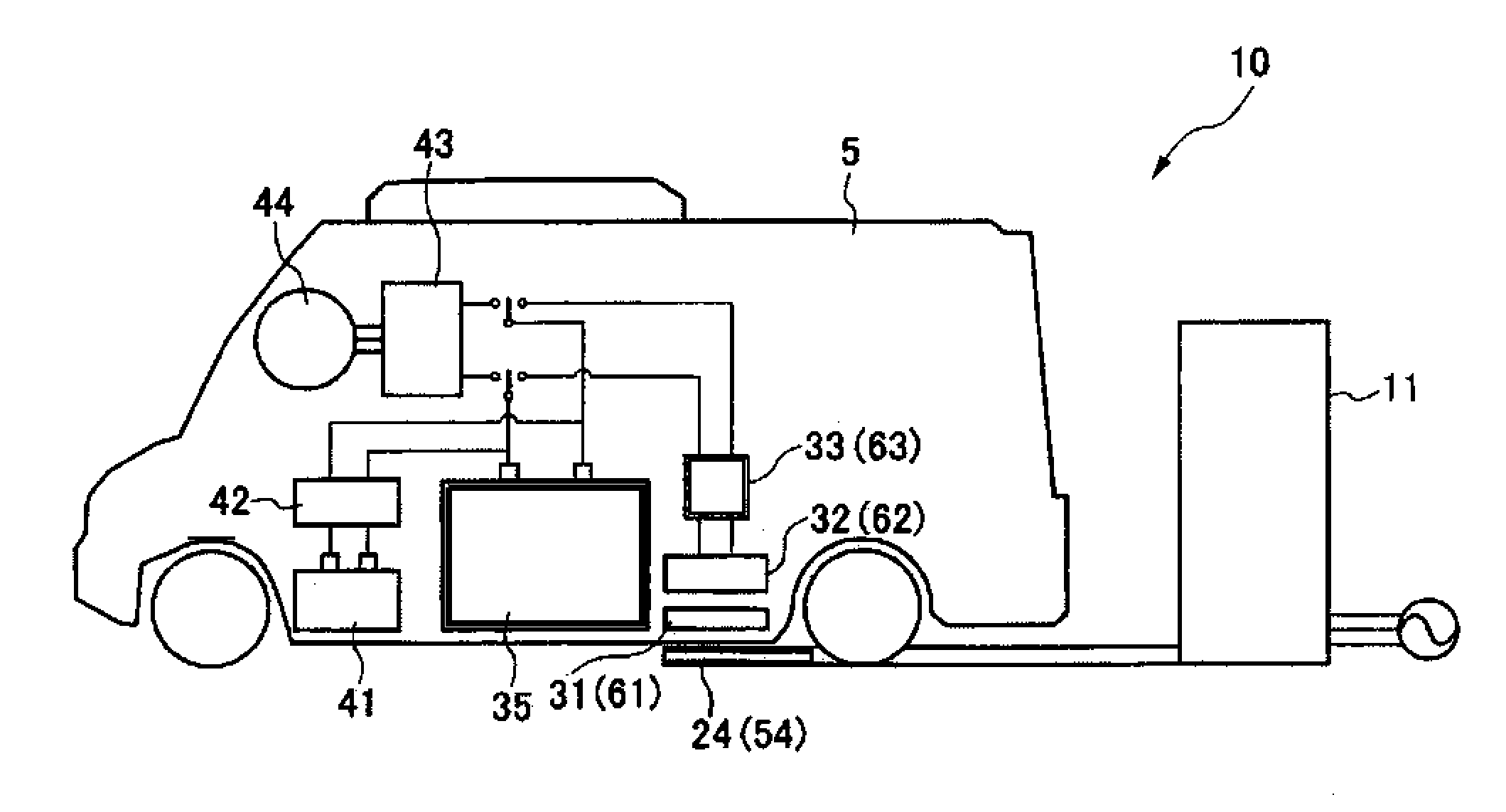
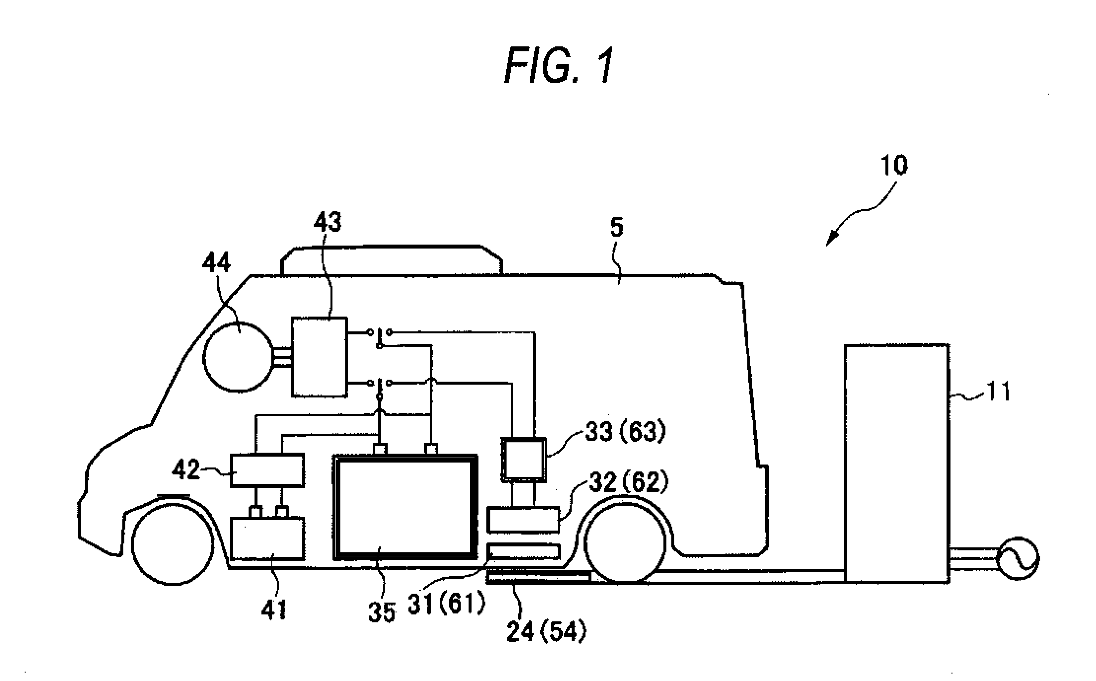
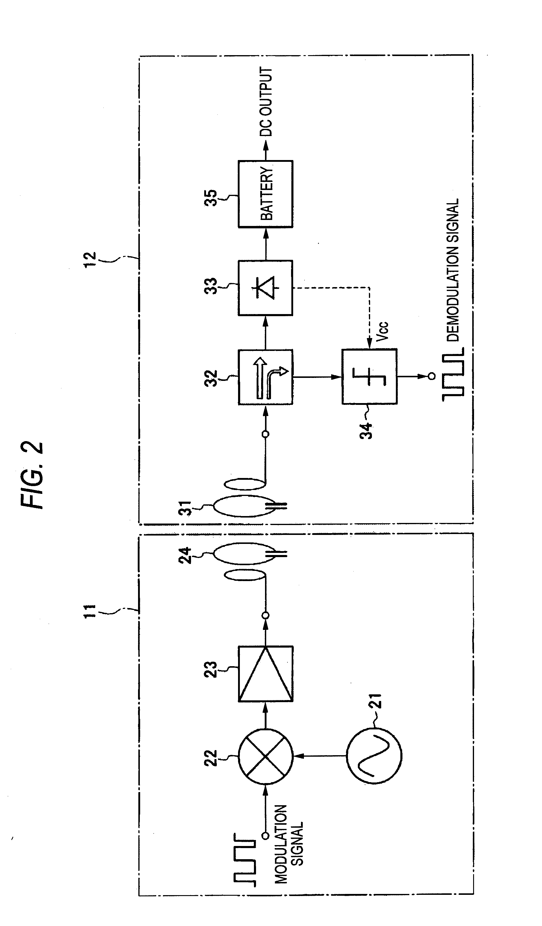
FIG. 2 is a block diagram showing the configuration of the wireless charging system for a vehicle according to the invention. As shown in this figure, the electric car 5 includes a charging apparatus 12. The charging apparatus 12 is supplied with electric power from the feeding apparatus 11 to thereby charge the battery 35.

The feeding apparatus 11 includes a carrier oscillator (electric power output section) 21 for outputting an AC power of a predetermined frequency, an ASK modulator (modulation section) 22 for superimposing a control signal on the AC power outputted from the carrier oscillator 21 according to a modulation method such as the ASK modulation, a power amplifier (electric power amplifying section) 23 for amplifying the AC power modulated by the ASK modulator, and a first resonance coil (communication terminal) 24 for outputting the AC power amplified by the power amplifier 23.

The carrier oscillator 21 outputs the AC power having the frequency in a range of 1 to 100 [MHz...

second embodiment

As shown in FIG. 3, the wireless charging system for a vehicle includes the feeding apparatus 13 and the charging apparatus 14.

The feeding apparatus 13 includes a carrier oscillator 51 for outputting an AC power, a hybrid distributor 55 for distributing the AC power outputted from the carrier oscillator 51 into two AC powers, an ASK modulator 52 for superimposing a control signal on one of the two AC powers distributed by the hybrid distributor 55 according to a modulation method such as the ASK modulation, a power amplifier 53 for amplifying the AC power modulated by the ASK modulator 52, and a first resonance coil 54 for outputting the AC power amplified by the power amplifier 53.

Further, the feeding apparatus is provided, between the power amplifier 53 and the first resonance coil 54, with a transmission / reception selection switch 56 for switching between the transmission and the reception. Furthermore, the feeding apparatus is provided with a power amplifier 57 for amplifying a...

third embodiment

FIG. 6 is a block diagram showing the configuration of the wireless charging system for a vehicle according to the As shown in this figure, a feeding apparatus 15 includes a carrier oscillator 71 for outputting a carrier signal for power transmission, an ASK modulator 72 for superimposing a control signal on the carrier signal outputted from the carrier oscillator 71 according to the modulation method such as the ASK modulation, a power amplifier 73 for amplifying the AC power thus modulated by the ASK modulator 72, and a first resonance coil 74 for outputting the AC power thus amplified by the power amplifier 73.

The carrier oscillator 71 outputs the AC power having the frequency in a range of 1 to 100 [MHz], for example, as an AC signal for power transmission.

The ASK modulator 72 modulates the AC power as the carrier signal according to the ASK (Amplitude Shift Keying) method. Although this embodiment is explained as to an example where the ASK method is employed as the modulation...


PUM


Abstract

A control signal is superimposed on an AC power at the time of charging the battery of an electric car in a non-contact manner by electric power outputted from a feeding apparatus. A feeding apparatus 11 includes a carrier oscillator 21 for outputting an AC power, an ASK modulator 22 for superimposing a control signal on the AC power outputted from the carrier oscillator 21 according to the ASK modulation method, a power amplifier 23 for amplifying the AC power modulated by the ASK modulator 22, and a first resonance coil 24 for outputting the AC power amplified by the power amplifier 23. A charging apparatus 12 to be provided on an electric car includes a second resonance coil 31 for receiving the AC power transmitted from the first resonance coil 24, an ASK demodulator 34 for demodulating the received AC power to thereby extract the control signal, and a rectifier 33 which rectifiers the received AC power to obtain a DC power and supplies the DC power to a battery 35.

Description

TECHNICAL FIELDThe present invention relates to a wireless charging system for a vehicle which transmits, in a non-contact manner, electric power outputted from a feeding apparatus to a battery mounted on a vehicle and, in particular, relates to a technique of communicating between the feeding apparatus and the vehicle in a manner of superimposing a control signal on an electric power signal transmitted to the vehicle from the feeding apparatus.BACKGROUND TECHNIQUEAs a charging system for charging electric power to the battery of an electric car, there is known one which is disclosed in JP-A-2006-74868 (patent document 1), for example. Since the charging system described in the patent document 1 is configured in a manner that a non-contact type charging system based on electromagnetic induction is employed to supply electric power for charging the battery to the vehicle in a non-contact manner to thereby charge the battery. Thus, the battery can be charged easily without requiring s...

Claims


Application Information

Patent Timeline
IPC IPC(8): H01F38/14
CPCB60L11/182B60L11/1838H02J7/025Y02T10/7005Y02T90/121Y02T90/128Y02T90/14Y02T90/163Y02T90/122Y02T10/7072H02J50/10H02J7/00034B60L53/62B60L53/126B60L53/122B60L53/66Y02T90/12Y02T90/16Y02T10/70H02J50/12H02J50/80B60L53/12
Inventor HIRAYAMA, MAKOTO
Owner YAZAKI CORP
Features
  • Generate Ideas
  • Intellectual Property
  • Life Sciences
  • Materials
  • Tech Scout
  • Unparalleled Data Quality
  • Higher Quality Content
  • 60% Fewer Hallucinations
Learn More