RF Hollow Cathode Plasma Generator

Inactive Publication Date: 2011-08-11
INST NUCLEAR ENERGY RES ROCAEC
View PDF5 Cites 20 Cited by
  • Summary
  • Abstract
  • Description
  • Claims
  • Application Information

AI Technical Summary

Benefits of technology

[0011]It is another objective of the present invention to provide an RF hollow cathode plasma source that can generate high density plasma with excellent uniformity in its distribution of working gas.
[0012]It is another objective of the prese

Problems solved by technology

Therefore, the application of the plasma is not efficient.
The design would not be possible without a thorough study of the flow field of the working gas.
As discuss

Method used


Image

  • RF Hollow Cathode Plasma Generator
  • RF Hollow Cathode Plasma Generator
  • RF Hollow Cathode Plasma Generator

Examples


Embodiment Construction

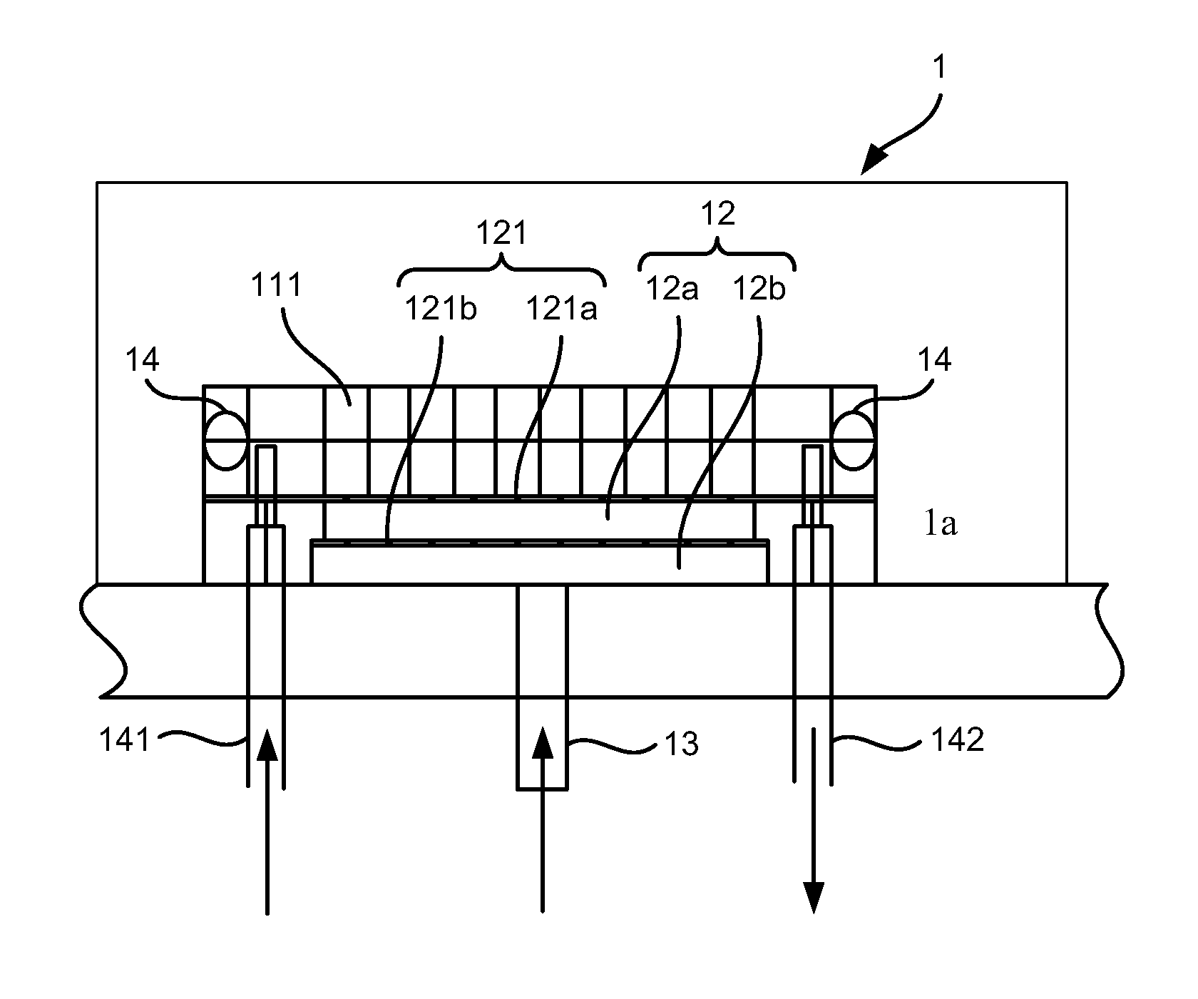
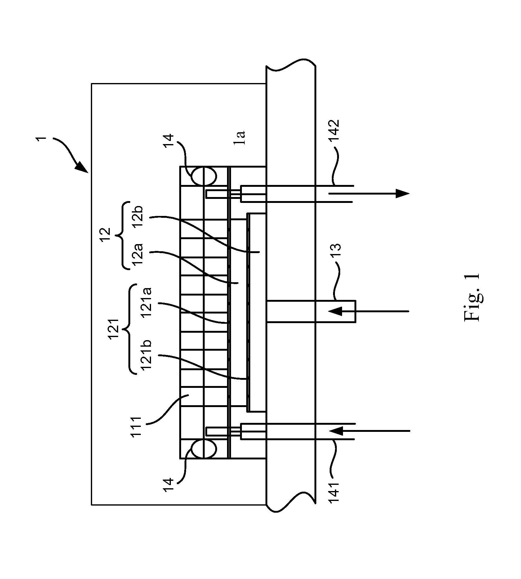
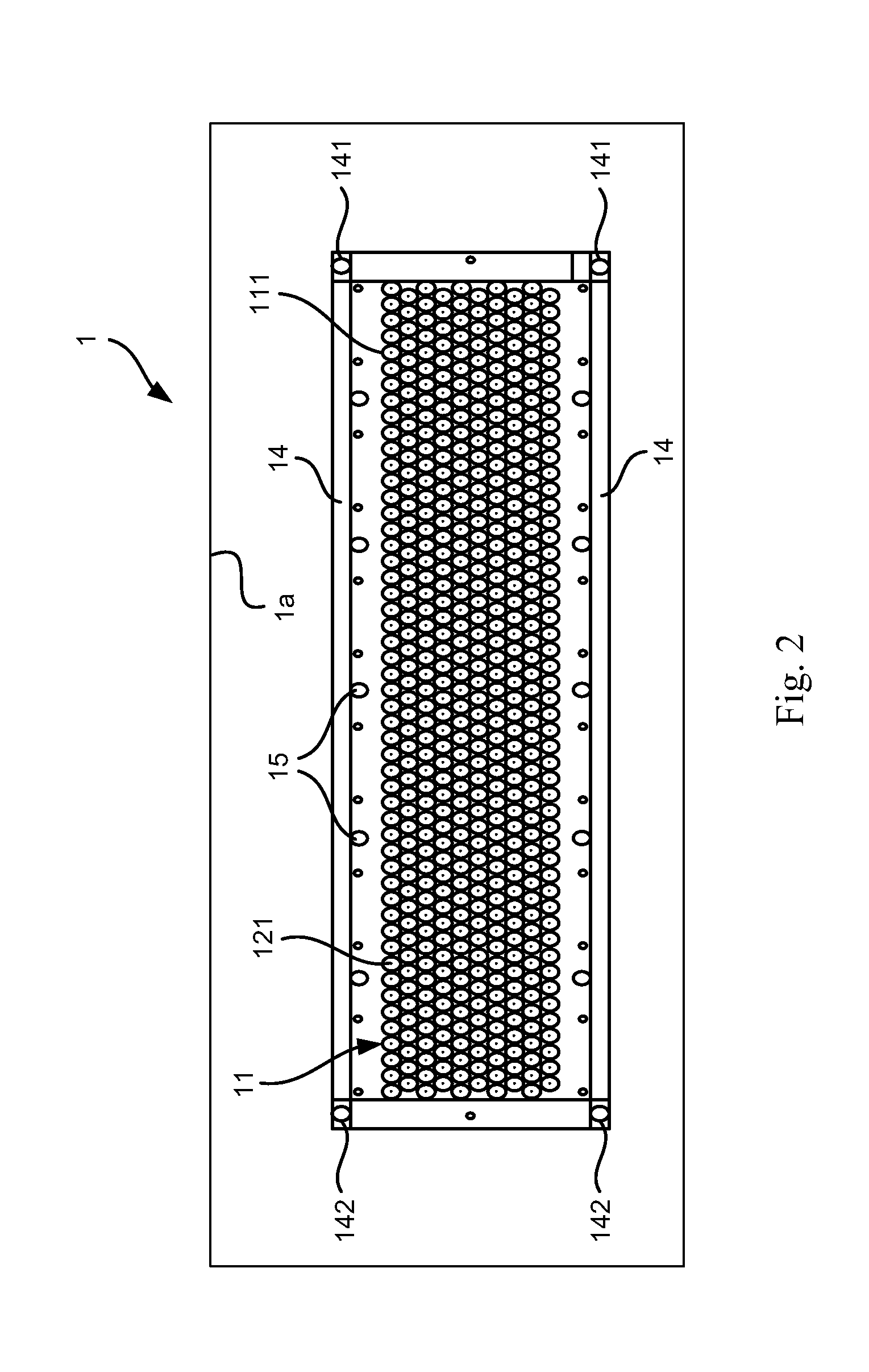
[0019]Referring to FIGS. 1 through 3, an RF hollow cathode plasma source includes a vacuum chamber 1a, a hollow cathode 11, at least two gas compartments 12, a gas pipe 13, a conduit and input power leads 15 according to the preferred embodiment of the present invention.

[0020]The hollow cathode 11 is disposed in the chamber 1a and electrically insulated from it. The hollow cathode 11 consists of a large number of apertures 111, in which there is a small gas entrance aperture 121a in the bottom of each aperture. Two conduits 14 are disposed along two sides of the hollow cathode 11. Two ends of each conduit are connected respectively with an entrance tube 141 and an exit tube 142.

[0021]The gas compartments 12a and 12b are parts of the hollow cathode 11 and are overlapped and located below the hollow cathode 11 within the chamber 1a. Each of the compartments 12a and 12b includes small apertures 121a and 121b, respectively. Each of the small apertures 121a and 121b is aligned with its r...


PUM

PropertyMeasurementUnit
Poweraaaaaaaaaa

Abstract

An RF hollow cathode plasma source consists of a vacuum chamber, a pipe, a hollow cathode, at least two compartments, a conduit and input electrodes. The pipe is inserted into the chamber for introducing working gas into the chamber. The hollow cathode is disposed in the chamber and formed with a large number of apertures. At least two compartments are located below the hollow cathode. Each of the compartments includes small apertures for uniformly spreading the working gas into the apertures of the hollow cathode. The conduit is disposed along two sides of the hollow cathode to circulate cooling water around the hollow cathode. The plural input power leads are arranged near the hollow cathode. The input power leads, the pipe and the conduits are connected to the hollow cathode though the electrically-insulated walls of the grounded vacuum chamber.

Description

FIELD OF THE INVENTION[0001]The present invention relates to a radio frequency (“RF”) hollow cathode plasma source.DESCRIPTION OF THE RELATED ARTS[0002]A typical plasma source consists of a pair of planar electrodes disposed in a vacuum chamber. Working gas such as argon or oxygen is introduced into the chamber after it is evacuated to the required vacuum condition. The pressure is about 10˜10−2 torr in the chamber during operation.[0003]A DC or pulsed DC electric power may be applied to the pair of planar electrode to generate a negative voltage and therefore an electric field. Accelerating to high energy by the electric field, electrons bombard and ionize the neutral working gas. Thus, plasma is generated.[0004]Alternatively, an RF (Radio frequency) electric power may be applied to the pair of planar electrodes to generate an alternating electric field. Accelerating to high energy by the alternating electric field, electrons hit and ionize the working gas. Thus, RF plasma is gener...

Claims


Application Information

Patent Timeline
IPC IPC(8): C23C16/00H05H1/24
CPCC23C16/509H01J37/32596H01J37/3244
Inventor TSENG, CHING-PEIHSIEH, CHENG-CHANGAI, CHI-FONGLEE, CHIA-CHENGLIN, DENG-LAIN
Owner INST NUCLEAR ENERGY RES ROCAEC
Why Eureka
Try Eureka