Active snubber circuit and power supply circuit

a technology of active snubber circuit and power supply circuit, which is applied in the direction of electric variable regulation, process and machine control, instruments, etc., can solve the problems of increased power consumption, difficult to acquire optimal on-off timing of power elements, and change of surge voltage into heat energy, etc., to reduce surge current and noise, improve power supply efficiency, and reduce power consumption

Inactive Publication Date: 2011-08-11
SANKEN ELECTRIC CO LTD
View PDF8 Cites 35 Cited by
  • Summary
  • Abstract
  • Description
  • Claims
  • Application Information

AI Technical Summary

Benefits of technology

[0016]Considering the above problems, an object of the invention is to provide an active snubber circuit and a power supply circuit that enable an optimal on-off timing of a sub-switching element to be easily obtained, providing no coil for signal to a transformer to prevent a structure of the transformer from being complicated and suppressing increase of power consumption during standby of a power source.
[0022]According to the aspects of the invention, it is possible to provide an active snubber circuit and a power supply circuit enabling an optimal on-off timing of a sub-switching element to be easily obtained, having a simple transformer and capable of reducing surge current and noise.

Problems solved by technology

However, when the snubber circuit is configured in a passive manner, the surge voltage is changed into heat energy, which is then consumed.
However, it is difficult to acquire an optimal on-off timing of a power element.
Hence, loss is always caused due to a resistance detecting the both-end voltage of the sub-switching element, so that power consumption is increased during the standby such as unload or light load.
However, since an extra tap is required for the transformer, spaces between the respective coils are necessary, so that a structure of the transformer is complicated and an outward size of the transformer should be enlarged.

Method used


Image

  • Active snubber circuit and power supply circuit
  • Active snubber circuit and power supply circuit
  • Active snubber circuit and power supply circuit

Examples


Embodiment Construction

[0030]Hereinafter, preferred illustrative embodiments of the invention will be described.

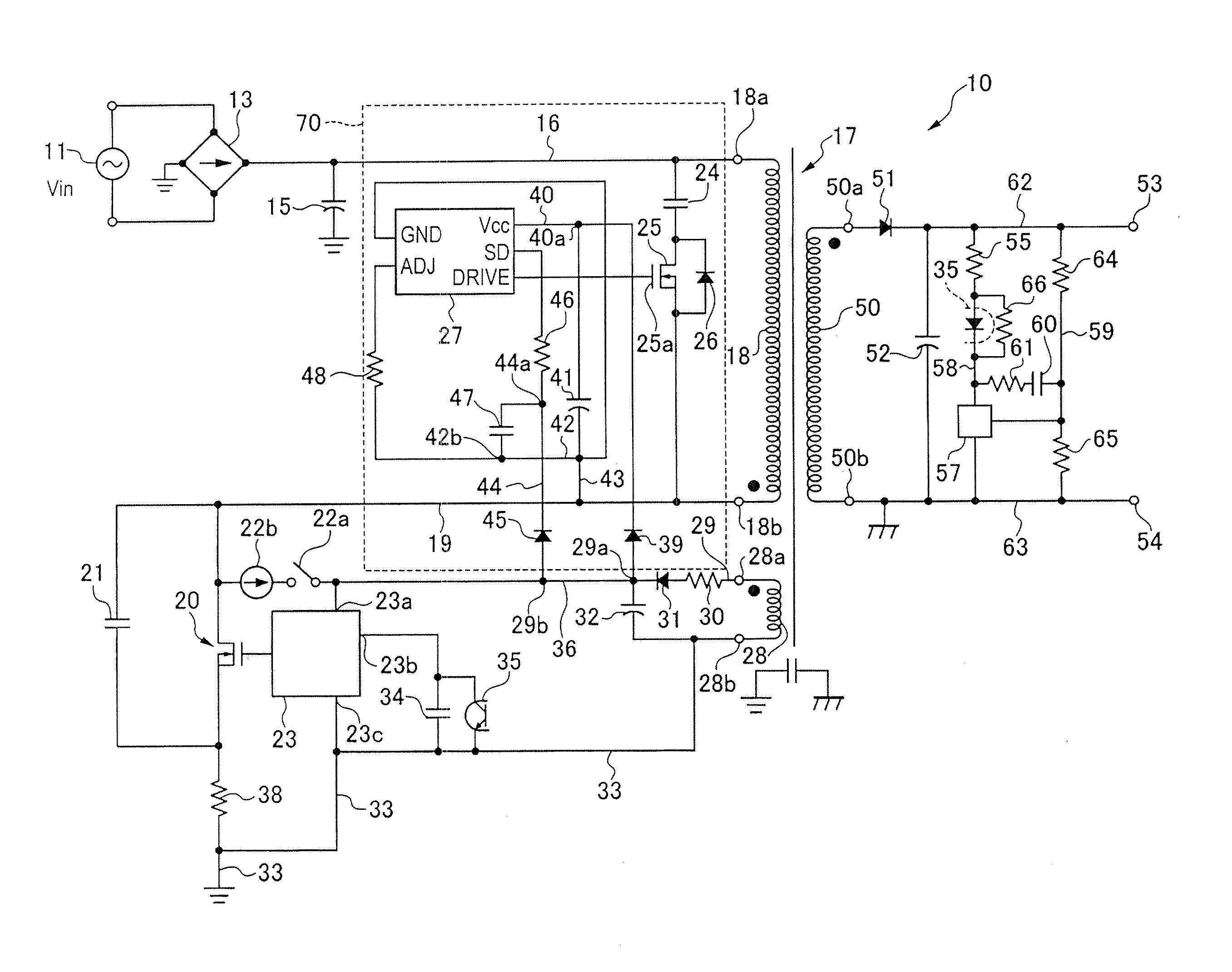
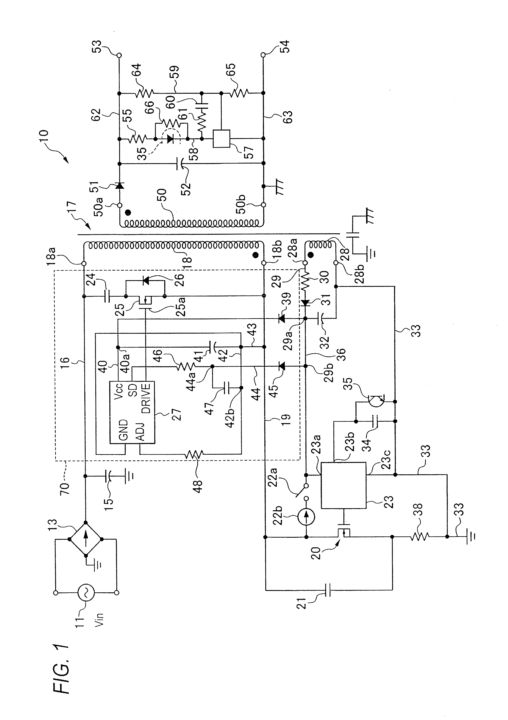
[0031]FIG. 1 is a circuit diagram showing a switching power supply circuit using an active snubber circuit according to an illustrative embodiment of the invention. In a switching power supply circuit 10 shown in FIG. 1, an alternating current (AC) voltage from an input power source 1 is supplied to a diode rectification bridge 13 and the rectified voltage is smoothed in a capacitor 15 for smoothing and then taken out as a smoothed direct current (DC) voltage. A line 16 to which the smoothed DC voltage is supplied is connected to one end 18a of a primary-side main coil 18 for excitation of a main transformer 17 for power transmission. The other end 18b of the primary-side main coil 18 is connected to a line 19.

[0032]The other end 18b of the primary-side main coil 18 is connected to a drain terminal of a main switching element 20 by the line 19 and a capacitor 21 is provided between the drain ter...


PUM


Abstract

An active snubber circuit for a switching power supply, in which a main switching element repeatedly operates an on-off operation so that current intermittently flows in a primary coil, has a capacitor for surge voltage absorption, a sub-switching element and a sub-control circuit controlling the sub-switching element. A circuit in which the capacitor for surge voltage absorption and the sub-switching element are connected in series is connected in parallel with the primary coil, and the sub-control circuit turns on the sub-switching element for a predetermined time period just after the main switching element is off.

Description

CROSS-REFERENCE TO RELATED APPLICATIONS[0001]This application claims priority from Japanese Patent Application No. 2010-027982 filed on Feb. 10, 2010, the entire subject-matter of which is incorporated herein by reference.BACKGROUND OF THE INVENTION[0002]1. Field of the Invention[0003]The present invention relates to an active snubber circuit and a power supply circuit, and more particularly, to an active snubber circuit and a power supply circuit capable of absorbing and reducing a surge voltage of a switching element that is used in a switching power supply device and the like.[0004]2. Description of the Related Art[0005]Heretofore, in a flyback converter (RCC) circuit, a snubber circuit is connected between primary coils of a flyback transformer so as to absorb and reduce a surge voltage of a main switching element. The snubber circuit includes a passive-type snubber circuit using an RCD snubber or charge accumulating diode and an active clamp-type snubber circuit (active snubber...

Claims


Application Information

Patent Timeline
Patent Type & Authority Applications(United States)
IPC IPC(8): H02M3/335H02H9/00
CPCH02M3/33569Y02B70/1491H02M2001/342Y02B70/10H02M1/342
Inventor YOSHINAGA, MITSUTOMO
Owner SANKEN ELECTRIC CO LTD
Why Eureka
Try Eureka