Spiral type fluid mixer and apparatus using spiral type fluid mixer

a fluid mixer and spiral-type technology, applied in the direction of gaseous fuels, transportation and packaging, fuels, etc., can solve the problems of large space for providing branched pipelines, large number of parts, and time-consuming, so as to prevent defects, prevent burns, and stabilize the temperature more

Inactive Publication Date: 2011-08-18
ASAHI YUKIZAI KOGYO CO LTD
View PDF7 Cites 28 Cited by
  • Summary
  • Abstract
  • Description
  • Claims
  • Application Information

AI Technical Summary

Benefits of technology

[0035]The parts of the spiral type fluid mixer of the present invention such as the main body part 11, cylindrical member 15, swirl blade 31, etc. may be made of any resin. Any of polyvinyl chloride, polypropylene (hereinafter referred to as “PP”), polyethylene, etc. may be used. In particular, when using a corrosive fluid as the fluid, polytetrafluoroethylene (hereinafter referred to as “PTFE”), polyvinylidene fluoride, tetrafluoroethylene-perfluoroalkyl vinyl ether copolymer resin (hereinafter referred to as “PFA”), or another fluororesin is preferable. If a fluororesin, use for a corrosive fluid is possible. Further, even if corrosive gas passes through the parts, there is no longer any concern over corrosion of the pipe members, so this is preferred. Further, the members forming the main body part or housing may be transparent or semitransparent members. This is preferable in that it enables the state of mixing of the fluid to be visually confirmed. Further, depending on the substance running through the fluid mixer, the parts may be made of iron, copper, copper alloy, brass, aluminum, stainless steel, or another metal.
[0036]The present invention is structured in the above way and has the following superior effects. (1) Even in a state where the concentration of a chemical temporarily becomes denser or thinner in a flow path, it is possible to mix the fluid while making the distribution of concentration of the fluid in the direction of flow uniform without any unevenness, possible to supply a chemical in a stable concentration, and possible to prevent defects due to changing concentrations of chemicals in various industrial fields. (2) Even in a state in which the temperature of the fluid temporarily becomes higher or becomes lower in a flow path, it is possible to mix the fluid while making the distribution of temperature of the fluid in the direction of flow uniform with no unevenness, possible to supply fluid by a stable temperature, possible to stabilize the temperature more in a hot water heater etc., and possible to prevent burns.

Problems solved by technology

In this case, there was the problem of the space for providing the branched pipelines ending up becoming larger.
Further, there was the problem that installation of such pipelines required a large number of parts and was both complicated and time-consuming.

Method used


Image

  • Spiral type fluid mixer and apparatus using spiral type fluid mixer
  • Spiral type fluid mixer and apparatus using spiral type fluid mixer
  • Spiral type fluid mixer and apparatus using spiral type fluid mixer

Examples


first embodiment

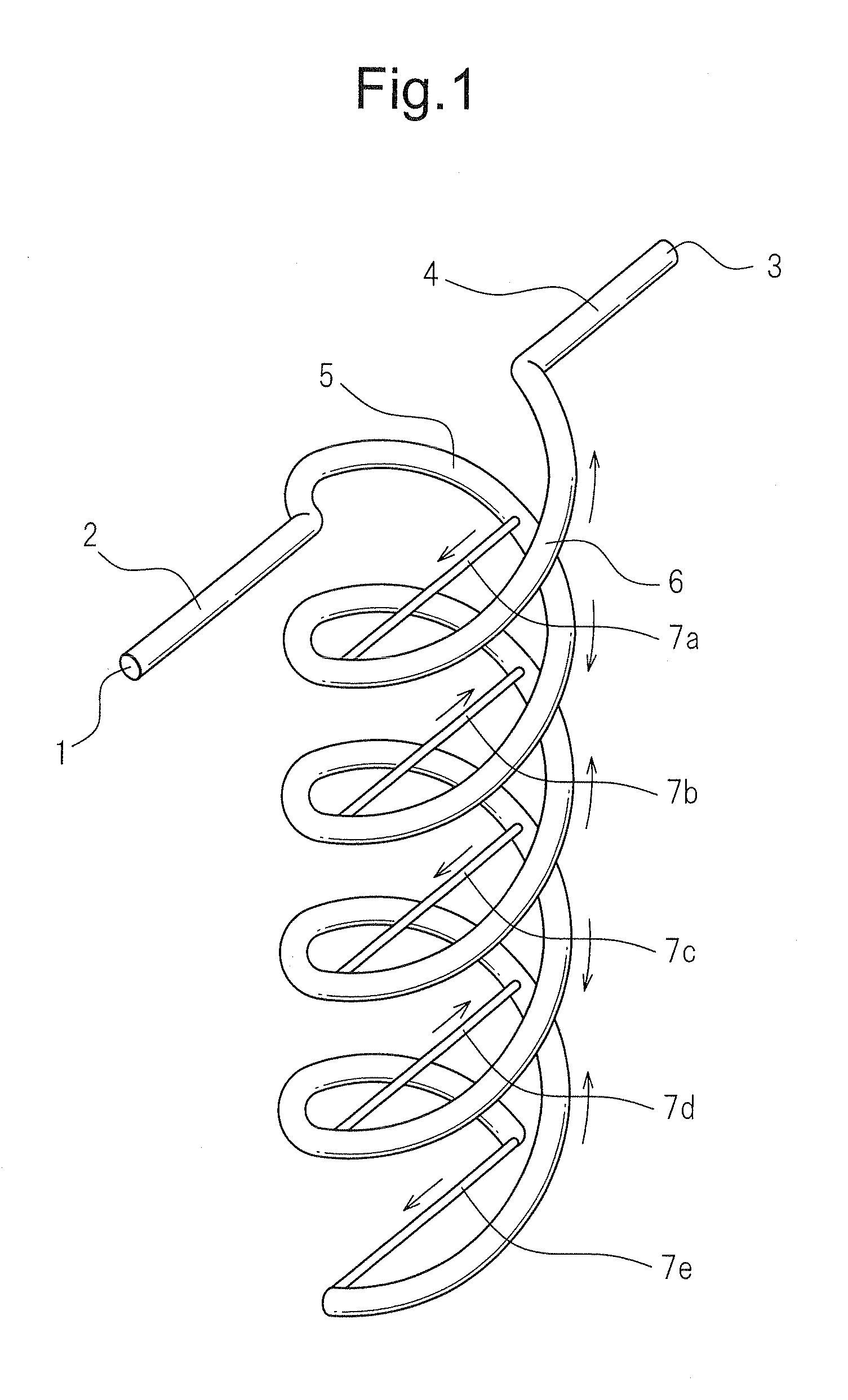
[0053]Below, a spiral type fluid mixer of the present invention will be explained with reference to FIG. 1.

[0054]The spiral type fluid mixer is provided with a fluid inlet 1 into which the fluid flows, a first flow path 2 which is connected to the fluid inlet 1, a fluid outlet 3 from which the fluid flows, and a second flow path 4 which is connected to the fluid outlet 3. A first spiral flow path 5 which is connected to the first flow path 2 and a second spiral flow path 6 which is connected to the second flow path 4 are arranged at a fixed interval so that centers of the spirals are on the same axial line. On the first spiral flow path 5, branch flow paths 7a to 7e which are respectively connected to any positions on the second spiral flow path 6 are provided at equal interval distances. Further, the ends parts of the first spiral flow path 5 and the second spiral flow path 6 which are not connected to the first and second flow paths 2 and 4 are provided with the branch flow path 7...

second embodiment

[0062]Next, the action of the spiral type fluid mixer of the present invention will be explained with reference to FIG. 5.

[0063]A PTFE main body part 11 is formed into a columnar shape. At the outer circumferential surface of the main body part 11, a first spiral groove 12 and a second spiral groove 13 are provided in parallel. The second spiral groove 13 is arranged between the grooves of the first spiral groove 12, while the first spiral groove 12 is arranged between the grooves of the second spiral groove 13. At the bottom surface of the first spiral groove 12, through holes 14 which form a plurality of branch flow paths which communicate with the second spiral groove 13 are provided at equal interval distances.

[0064]The cylindrical member 15 forming the PP housing is formed into a substantially cylindrical shape. The inside diameter of the cylindrical member 15 is formed to be substantially the same as the outside diameter of the main body part 11. The member is fit and fastened...

sixth embodiment

[0066]Next, the action of the spiral type fluid mixer of the present invention will be explained.

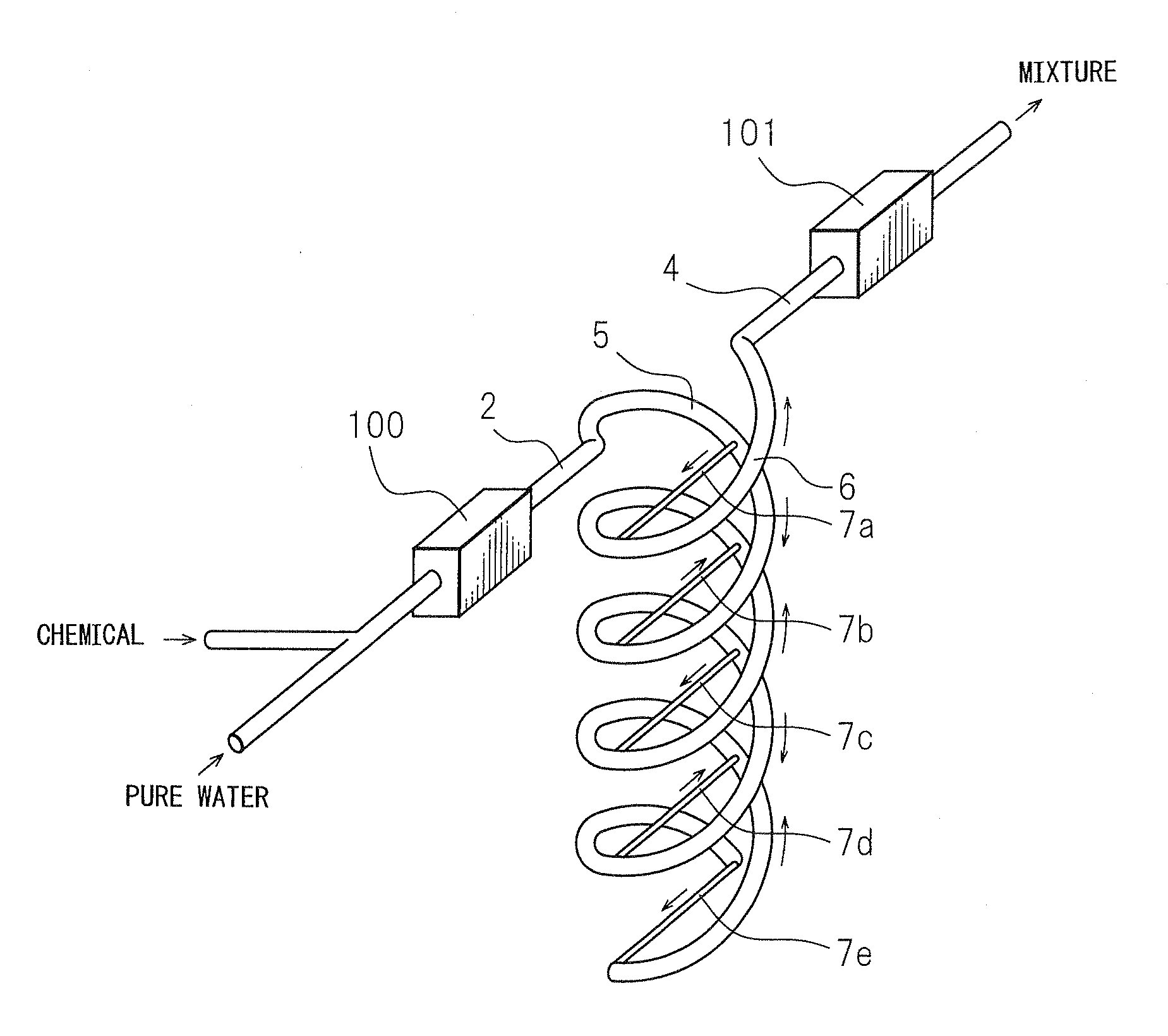
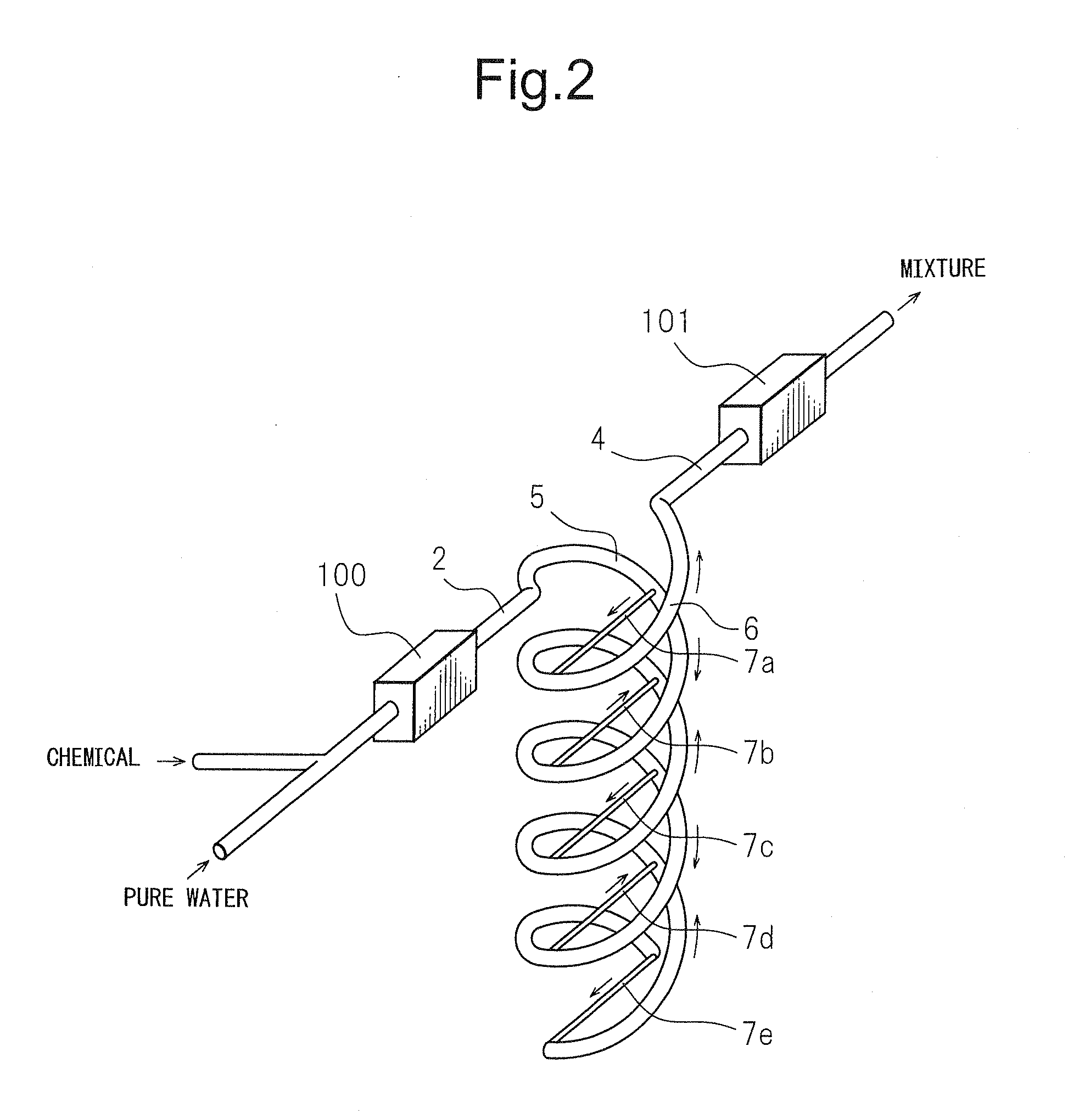
[0067]Water and a chemical are mixed and flow from an upstream side of the spiral type fluid mixer. When they flow in a state with the concentration of the chemical temporarily denser, the partially denser concentration chemical flowing through the flow path flows in from the fluid inlet 18, passes through the first flow path 20, and flows to the first spiral flow path 16. The partially denser concentration chemical which flows through the first spiral flow path 16 flows while being divided by the through holes 14. The partially denser concentration chemical flows through the second spiral flow path 17 with a time difference to be mixed with the not denser concentration chemical whereby the chemical is mixed to become uniform of the fluid in the direction of flow. It then can pass through the second flow path 21 and flow out from the fluid outlet 19. The action of making the distribution...


PUM

PropertyMeasurementUnit
circumferenceaaaaaaaaaa
areaaaaaaaaaaa
shapeaaaaaaaaaa

Abstract

A spiral type fluid mixer which enables mixing by a distribution of concentration or distribution of temperature in a flow direction of the fluid made uniform without unevenness and which is compact and enables easy piping work is provided. This spiral type fluid mixer is provided with a fluid inlet, a first flow path which is connected to the fluid inlet, a first spiral flow path which is connected to the first flow path, a plurality of branch flow paths which are branched from the first spiral flow path, a second spiral flow path to which the plurality of branch flow paths are connected, a second flow path which is connected to the second spiral flow path, and a fluid outlet which is connected to the second flow path, the plurality of branch flow path being branched from different positions of the first spiral flow path and being connected with the second spiral flow path at different positions of the second spiral flow path.

Description

TECHNICAL FIELD[0001]The present invention relates to a spiral type fluid mixer which is used for fluid transport piping in various industrial fields such as chemical factories, the semiconductor production field, food field, medical field, biotech field, etc., in particular relates to a spiral type fluid mixer and apparatus using a spiral type fluid mixer able to mix fluid while making the distribution of concentration or distribution of temperature of the fluid in the direction of flow uniform without any unevenness.BACKGROUND ART[0002]In the past, as the method of attaching a device inside of a pipe to uniformly mix fluid flowing through the inside of the pipe, as shown in FIG. 12, use of a swirl blade type static mixer element 81 has been the general practice (see, for example, Japanese Patent Publication (A) No. 2001-205062). Usually, the static mixer element 81 is comprised of a square plate twisted 180 degrees about its longitudinal axis as a minimum unit member and has a plu...

Claims


Application Information

Patent Timeline
Patent Type & Authority Applications(United States)
IPC IPC(8): B01F15/02B01F23/00B01F23/10
CPCB01F5/0646B01F5/0647C10L3/10B01F5/0657B01F5/0656B01F25/4341B01F25/434B01F25/4331B01F25/433B01F23/40B01F23/50B01F25/00
Inventor HANADA, TOSHIHIRO
Owner ASAHI YUKIZAI KOGYO CO LTD
Why Eureka
Try Eureka