Formable light weight composite material systems and methods

a composite material and light weight technology, applied in the field of fiberfilled polymeric materials and composite materials, can solve the problem of difficult proposition of having a “one size fits all” material system, and achieve the effect of reducing the transmission of sound, high strength to weight ratio, and attractive performance characteristics

Active Publication Date: 2011-08-18
PRODIVE RES
View PDF105 Cites 58 Cited by
  • Summary
  • Abstract
  • Description
  • Claims
  • Application Information

AI Technical Summary

Benefits of technology

[0011]A further aspect of the teachings is directed at a welded structure including a composite material, such as a composite material described herein, welded to steel (e.g., resistance welded), to a metal other than steel, to a substantially identical composite material, to a different composite material, or any combination thereof. Surprisingly, the light weight composite material may have a polymeric layer including a quantity and an arrangement of metallic fibers sufficient to allow electrical conductivity so that the composite material is capable of being welded (e.g., using conventional equipment and processes of a type used for resistance welding steel in existing vehicle production lines), and yet sufficiently low so that the composite material affords attractive performance characteristics such as a relatively high strength to weight ratio, coatability, reducing the transmission of sound through the material or any combination thereof.

Problems solved by technology

Unfortunately cost and performance requirements vary from technological field to technological field, or even between different applications within a technological field, so the ability to have a “one size fits all” material system is a difficult proposition.

Method used


Image

  • Formable light weight composite material systems and methods
  • Formable light weight composite material systems and methods
  • Formable light weight composite material systems and methods

Examples


example 1

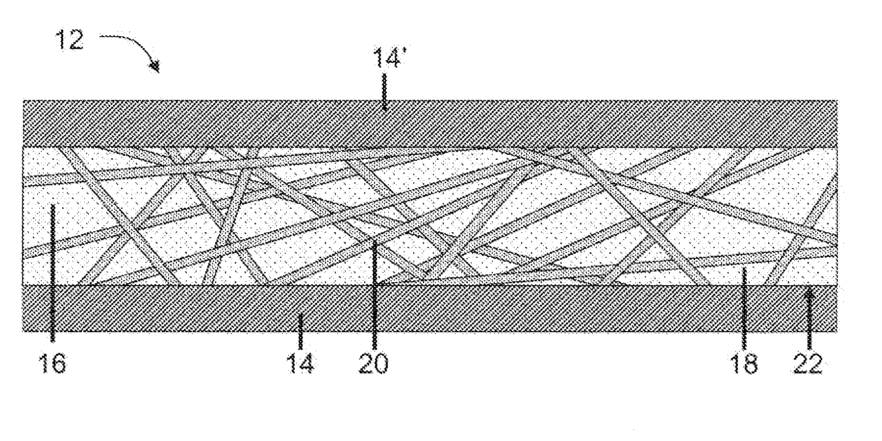
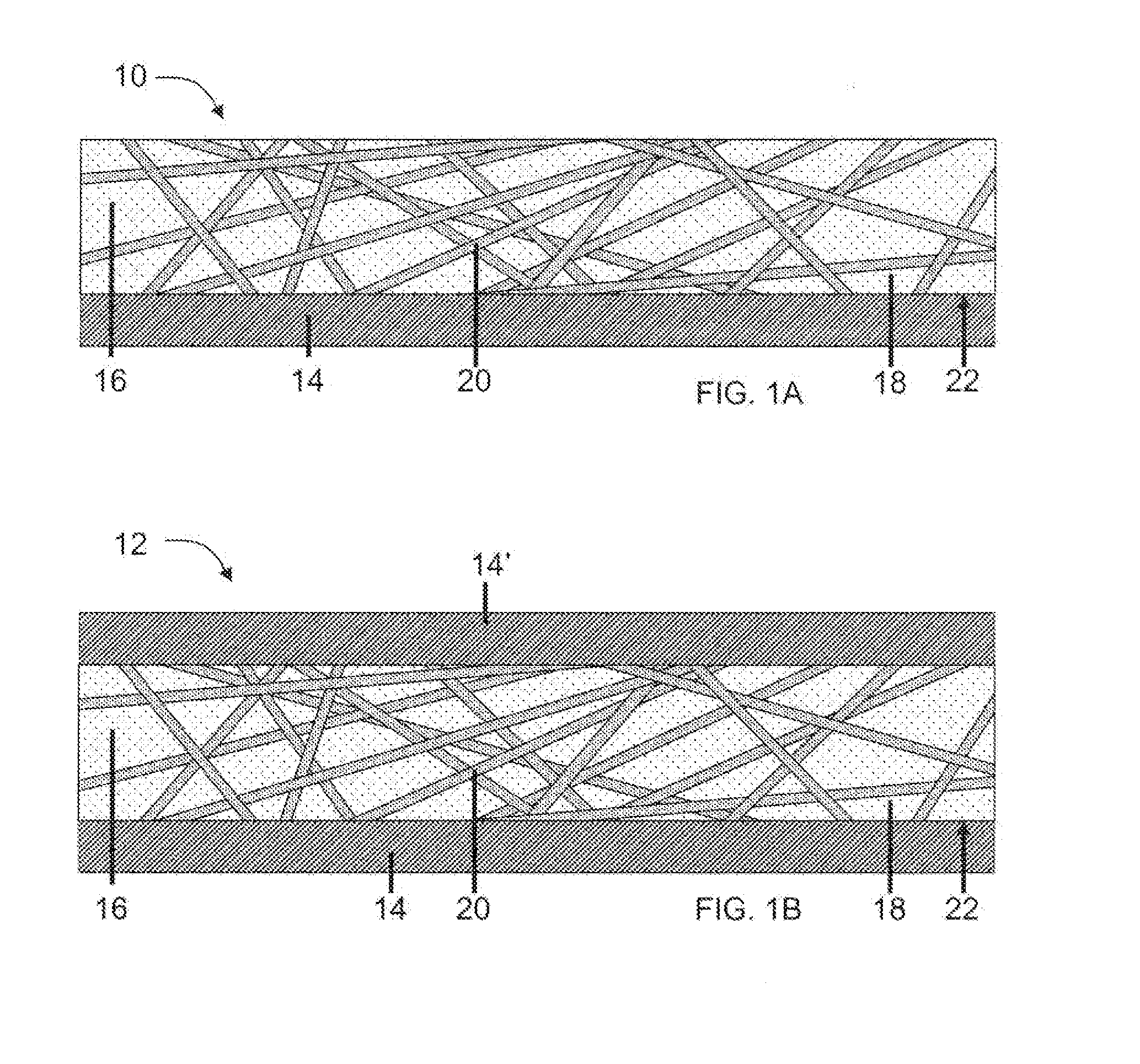
[0131]A filled thermoplastic material is prepared by mixing about 15 volume % low carbon steel fibers having a diameter from about 4 to about 40 μm, and a length from about 1 to about 10 mm and about 85 volume % of a copolyamide of about 50 wt. % nylon 6 and about 50 wt. % nylon 6,9 (the copolymer characterized by an elastic modulus of about 300 MPa measured according to ISO 527-2, a melting point of about 130° C. as measured according to ISO 11357, and an elongation at break of about 900% measured according to ISO 527-3). The filled thermoplastic material is mixed at a temperature from about 190° C. to about 250° C. The filled thermoplastic material is then placed between two sheets of low carbon steel, each having a thickness of about 0.2 mm. The materials are then pressed at a temperature from about 200° C. to about 230° C. with a pressure of about 1 to about 22 MPa. The composite material has a core thickness of the filled thermoplastic material of about 0.4 mm. The composite ma...

example 2

[0132]A composite material is prepared using the same materials, composition, and method as Example 1, except the fibers are replaced with low carbon fibers having a generally rectangular cross-section in the direction transverse to the length of the fibers. The fibers have an average length of about 2.3 mm. The average cross-sectional area of the fibers is about 0.0045 mm2. The ratio of the width to the thickness of the fibers is about 2 to 8. The composite material has a thickness of about 0.8 mm. The composite material is stacked with a sample of cold rolled steel having a thickness of about 0.8 mm. The stack is placed in a spot welding machine between a pair of weld tips having a diameter of about 13 mm. A force of about 2.2 kNt is applied to the weld tips. The resistivity of the composite material in the through-thickness direction is determined while under force of 2.2 kNt. Thus determined, the electrical resistivity of Example 2 composite material is about 0.1 Ω·cm or less. W...

example 3

[0133]A composite material is prepared using the same materials, composition, and method as Example 1, except the metal sheets are replaced by 0.2 mm thick sheets of a high strength steel having a yield strength of about 350 MPa, a tensile strength of about 460 MPa, and an elongation of about 22%. The composite material is expected to have a yield strength of about 193 MPa, a tensile strength of about 253 MPa, and an elongation of about 22%. The density of the composite material is calculated to be about 34% less than a monolithic sheet of the low carbon steel having the same thickness (about 0.8 mm). The composite material is calculated have a yield strength that is about 50 MPa or more higher than the yield strength of the monolithic sheet of low carbon steel having the same thickness. The composite material is calculated to have a tensile strength that is at least about 90% of the tensile strength of the monolithic sheet of low carbon steel having the same thickness. The composit...


PUM

PropertyMeasurementUnit
melting pointaaaaaaaaaa
weight average lengthaaaaaaaaaa

Abstract

The present invention relates to filled polymeric materials including a polymer and a mass of metallic fibers distributed within the polymer, and to light weight composites which comprise at least a pair of metallic layers and a polymeric layer interposed between the pair of metallic layers, the polymeric layer containing the filled polymeric material. The composite materials of the present invention may be formed using conventional stamping equipment at ambient temperatures. Composite materials of the present invention may also be capable of being welded to other metal materials using a resistance welding process such as resistance spot welding. Preferred composite materials include one or any combination of the following features: metallic fibers that are ribbon fibers; a polymer selected from a polyolefin, a polyamide, or a combination thereof; or a metallic layer (e.g., one or both of the pair of metallic layers) having a surface facing the filled polymeric material that is untreated.

Description

CLAIM OF BENEFIT OF FILING DATE[0001]The present invention claims the benefit of the filing date of U.S. Provisional Patent Application Nos. 61 / 304,640 (filed by Mizrahi et al. on Feb. 15, 2010), 61 / 371,360 (filed by Mizrahi et al. on Aug. 6, 2010), 61 / 377,599 (filed by Mizrahi on Aug. 27, 2010), and 61 / 387,164 (filed by Mizrahi on Sep. 28, 2010), the contents of which are hereby incorporated by reference in their entirety.FIELD OF THE INVENTION[0002]The present invention relates generally to fiber-filled polymeric materials, and to composite materials that include a layer of the fiber-filled polymeric material, and more particularly to sandwich composites that include a layer of the fiber-filled polymeric material and a metallic layer.BACKGROUND[0003]In International Patent Application Publication WO 2010 / 021899 (published on Feb. 25, 2010 by Mizrahi, and incorporated herein by reference in its entirety), there are described unique and new light weight composite materials and assoc...

Claims


Application Information

Patent Timeline
Patent Type & Authority Applications(United States)
IPC IPC(8): B32B5/16B23K20/06B32B15/085B32B15/088C08K3/08B29C59/02
CPCB32B15/02B32B15/08B32B15/18B32B27/20B32B27/32Y10T428/12444C08J5/041C08J5/10C08K7/06Y10T428/256B32B27/34B32B7/10B32B15/085B32B15/088B32B27/281B32B27/285B32B27/302B32B27/36B32B27/365B32B27/40B32B2250/02B32B2255/06B32B2255/10B32B2255/26B32B2262/103B32B2264/105B32B2264/108B32B2270/00B32B2274/00B32B2307/102B32B2307/20B32B2307/202B32B2307/208B32B2307/21B32B2307/54B32B2307/702B32B2307/704B32B2307/714B32B2307/718B32B2307/7242B32B2307/7265B32B2307/732B32B2439/00B32B2553/00B32B2605/08B32B2607/00Y10T428/31681Y10T428/31605Y10T428/31507Y10T428/31692Y10T428/31696Y10T428/249951Y10T428/31678Y10T428/2495B32B2250/03B32B2250/40B32B2605/00B32B27/06
Inventor MIZRAHI, SHIMONNARKIS, MOSHE
Owner PRODIVE RES
Why Eureka
Try Eureka