
Novel amphiphilic block copolymer, method for manufacturing the same, and polymer electrolyte membrane using the same

Active Publication Date: 2011-08-18
HYUNDAI MOTOR CO LTD +1
View PDF2 Cites 6 Cited by
  • Summary
  • Abstract
  • Description
  • Claims
  • Application Information

AI Technical Summary

Benefits of technology

[0009]The present invention provides a novel amphiphilic block copolymer designed to have suitably high hydrogen ion conductivity and to exhibit excellent mechanical properties, a method for manufacturing the amphiphilic block copolymer, and a polymer electrolyte membrane using the amphiphilic block copolymer.

Problems solved by technology

Although the fluorine electrolyte membranes have high chemical and mechanical stability and show excellent ion conductivity, the manufacturing cost is high due to a complicated manufacturing process and they show significant performance deterioration at a temperature of more than 80° C. Accordingly, hydrocarbon electrolyte membranes such as PAES, sPEEK, sPPBP, PI, etc. have been reported.
However, a large amount of hydrophilic groups are required to improve the ion conductivity, which can cause a problem in the dimensional stability due to high moisture-containing properties of the membrane.
The low dimensional stability has a bad effect on the manufacturing process of a membrane-electrode assembly (MEA) and its long-term stability.
However, the manufacturing cost is high and they show significant performance deterioration at a temperature of more than 80° C. Especially, in the case where the polymer electrolyte membrane fuel cell is operated at a high temperature of more than 100° C., (1) the resistance of platinum catalyst to impurities is increased, (2) the reaction rate at oxidation and reduction electrodes is increased, (3) the management of water in the fuel cell is easy, and (4) the cooling system is simplified.
However, in cases where these engineering plastics are used, the microphase separation between the hydrophilic and hydrophobic components, which is required to form ion channels, is not satisfactory.

Method used


Image

  • Novel amphiphilic block copolymer, method for manufacturing the same, and polymer electrolyte membrane using the same
  • Novel amphiphilic block copolymer, method for manufacturing the same, and polymer electrolyte membrane using the same
  • Novel amphiphilic block copolymer, method for manufacturing the same, and polymer electrolyte membrane using the same

Examples


preparation example 1

Synthesis of Poly(arylene sulfone ether ketone) Macroinitiator

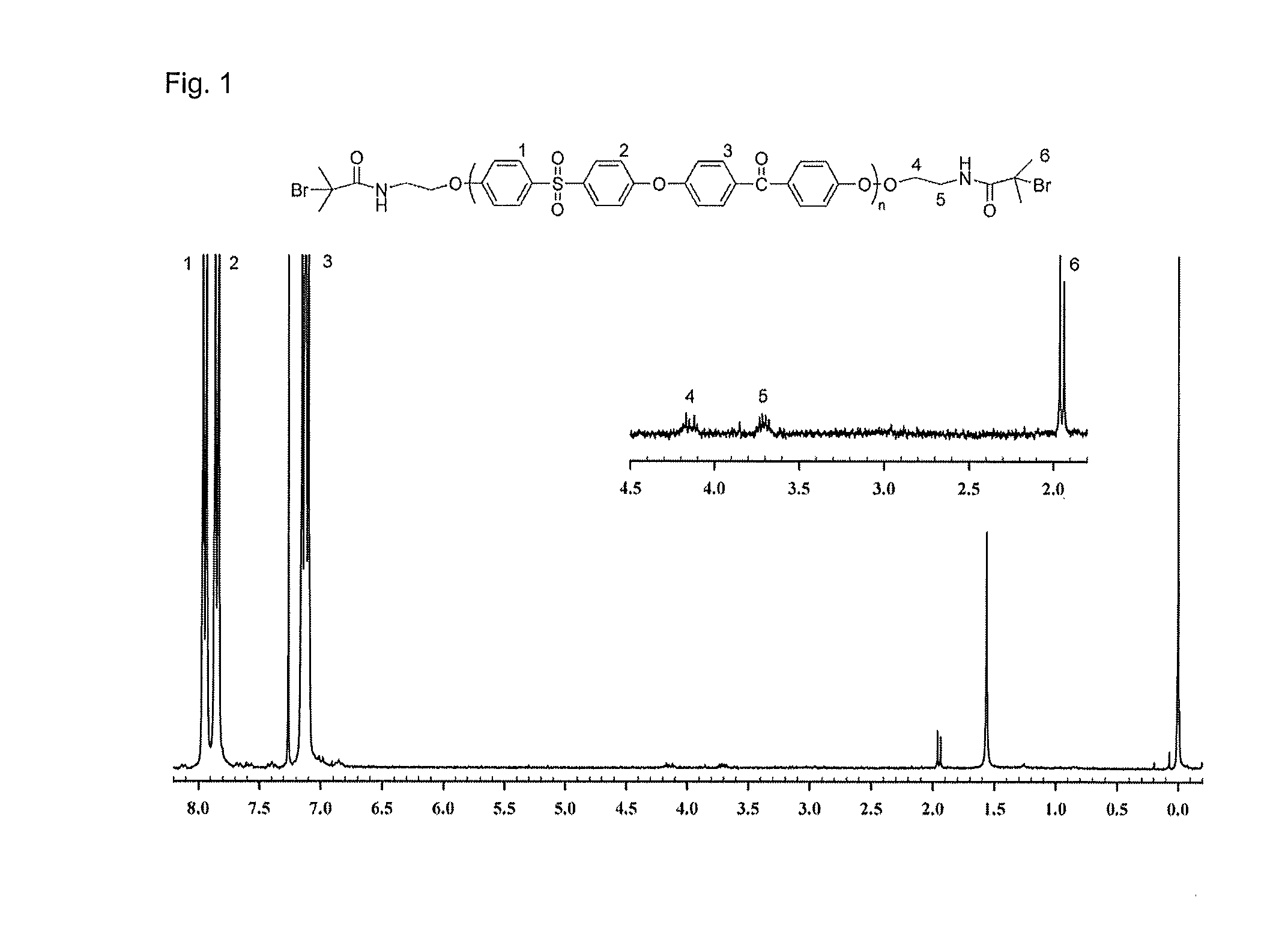
[0045]The overall synthesis method according to certain preferred embodiments is represented by the following formula 1:

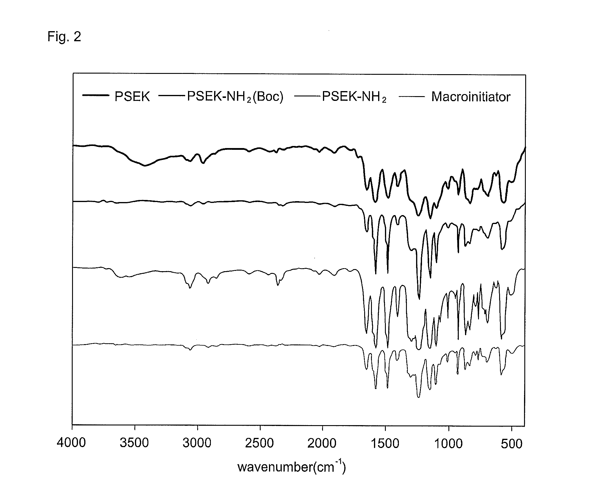
[0046]Accordingly, the poly(arylene sulfone ether ketone) macroinitiator was synthesized by four steps such as the synthesis of poly(arylene sulfone ether ketone), the substitution of the end group with an amine group protected by a butoxycarbonyl group (Boc), the removal of the protecting butoxycarbonyl group (Boc), and the introduction of bromine into the end group.

[0047]In a first exemplary embodiment, condensation polymerization was used to synthesize the poly(arylene sulfone ether ketone) in the form of a rod having excellent thermal and mechanical stability. 5.085 g (0.02 mol) of 4,4′-difluorodiphenylsulfone (DFDS), 4.328 g (0.02 mol) of 4,4′-dihydroxybenzophenone (DHBP), and 2.9024 g (0.021 mol) of K2CO3 were placed in a three-necked round flask, and sulfonate was added thereto under argon atmosph...

preparation example 2

Synthesis of PSEK-b-poly(styrene-co-acrylonitrile)

[0052]The overall synthesis method according to another exemplary embodiment is represented by the following formula 2:

[0053]A PSEK-b-poly(styrene-co-acrylonitrile) (PSEK-b-PSAN) block copolymer was synthesized by copolymerizing the PSEK macroinitiator, which was synthesized by an activator regenerated by electron transfer atom transfer radical polymerization (ARGET ATRP), with styrene and acrylonitrile. In a first exemplary embodiment, 0.549 mg (4.08×10⁻⁶ mol) of CuCl2 was placed in a Schlenk flask, and the flask was degassed under vacuum and filled with argon two times. Then, 15.6 ml (1.36×10⁻¹ mol) of purified styrene, 5.82 ml (8.84×10⁻² mol) of acrylonitrile, and 33.9 μl (1.22×10⁻⁴ mol) of Me6TREN were added thereto and sufficiently stirred. In a further preferred embodiment, the resulting solution was subjected to a freeze-pump-thaw process two times to remove the dissolved oxygen in the reaction flask. 0.400 g (1.6×10⁻² mol) of...

preparation example 3

Introduction of Sulfonic Acid Group into PSEK-b-poly(styrene-co-acrylonitrile)

[0055]The entire introduction method according to further exemplary embodiments is represented by the following formula 3:

[0056]Sulfonation reaction was carried out to introduce a hydrophilic group into the block copolymer. First, 5 ml of purified methylene chloride and 0.95 ml (1.00×10⁻² mol) of acetic anhydride were placed in a two-necked round flask to prepare 1 M of acetyl sulfate, a reactant for the sulfonation. 0.35 ml (6.57×10⁻³ mol) of sulfuric acid was slowly added thereto under ice bath.

[0057]The block copolymer to be sulfonated was placed in a two-necked flask and dissolved in 20 ml of purified methylene chloride. While maintaining the reaction temperature at 55° C., 1 M of acetyl sulfate was added 0.6 to 1.2 times the number of styrene in each block and refluxed for 4 hours. Methanol was added to the solution to terminate the reaction, and all the solvents were removed under reduced pressure. T...


PUM

PropertyMeasurementUnit
Temperatureaaaaaaaaaa
Percent by massaaaaaaaaaa

Abstract

The present invention provides an amphiphilic block copolymer, a method for manufacturing the same, and a fuel cell membrane using the same. According to preferred embodiments, the amphiphilic block copolymer may contain poly(arylene sulfone ether ketone) (PSEK) as a hydrophobic component and poly(sulfonated styrene-co-acrylonitrile) (PSSAN) as a hydrophilic component. According to other preferred embodiments, polymer electrolyte membrane manufactured using the amphiphilic block copolymer has certain advantages in that the hydrogen ion conductivity is not reduced even at a high temperature of more than 100° C. but is rather increased and the thermal and chemical dimensional stability is excellent.

Description

CROSS-REFERENCE TO RELATED APPLICATION[0001]This application claims under 35 U.S.C. §119(a) the benefit of Korean Patent Application No. 10-2010-0013909 filed Feb. 16, 2010, the entire contents of which are incorporated herein by reference.BACKGROUND[0002](a) Technical Field[0003]The present disclosure relates, generally, to an electrolyte membrane for a fuel cell. More particularly, it relates to a novel amphiphilic block copolymer, a method for manufacturing the same, and a polymer electrolyte membrane using the same.[0004](b) Background Art[0005]As an electrolyte membrane for a polymer electrolyte membrane fuel cell (PEMFC), fluorine electrolyte membranes are typically used. Although the fluorine electrolyte membranes have high chemical and mechanical stability and show excellent ion conductivity, the manufacturing cost is high due to a complicated manufacturing process and they show significant performance deterioration at a temperature of more than 80° C. Accordingly, hydrocarb...

Claims


Application Information

Patent Timeline
IPC IPC(8): C08F293/00
CPCC08F293/00C08G65/48Y02E60/523H01M2300/0082H01M8/1072H01M8/1044H01M8/1027C08G75/23C08G2261/722C08G2650/40C08L71/00C08L2205/05H01M8/1023H01M8/1025C08L25/06C08F8/36C08F293/005C08L25/04Y02P70/50Y02E60/50
Inventor JO, WON HOKIM, TAE-ANNHWANG, IN CHULKWON, NAK HYUN
Owner HYUNDAI MOTOR CO LTD
Learn More