[0006]The invention is an assembly of elements to collect
solar energy and rain water.
Solar energy is converted to
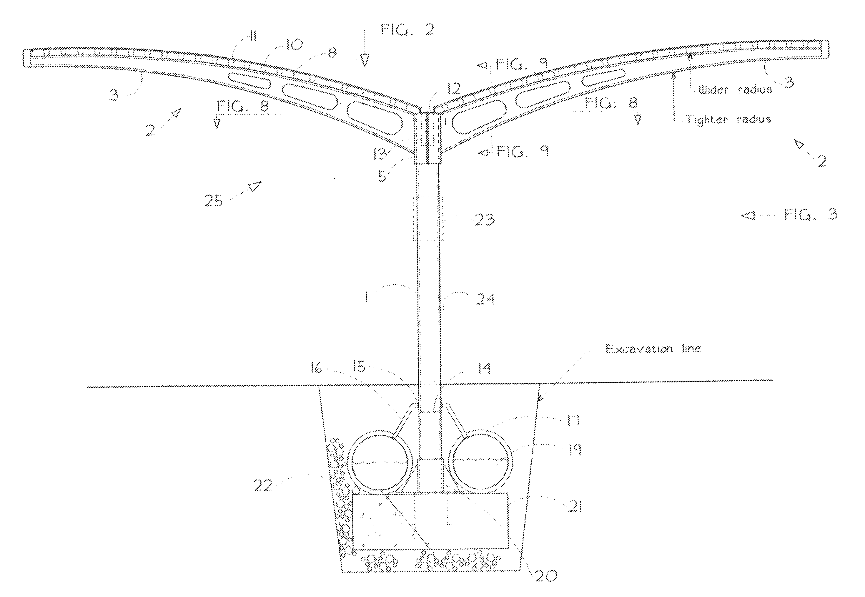
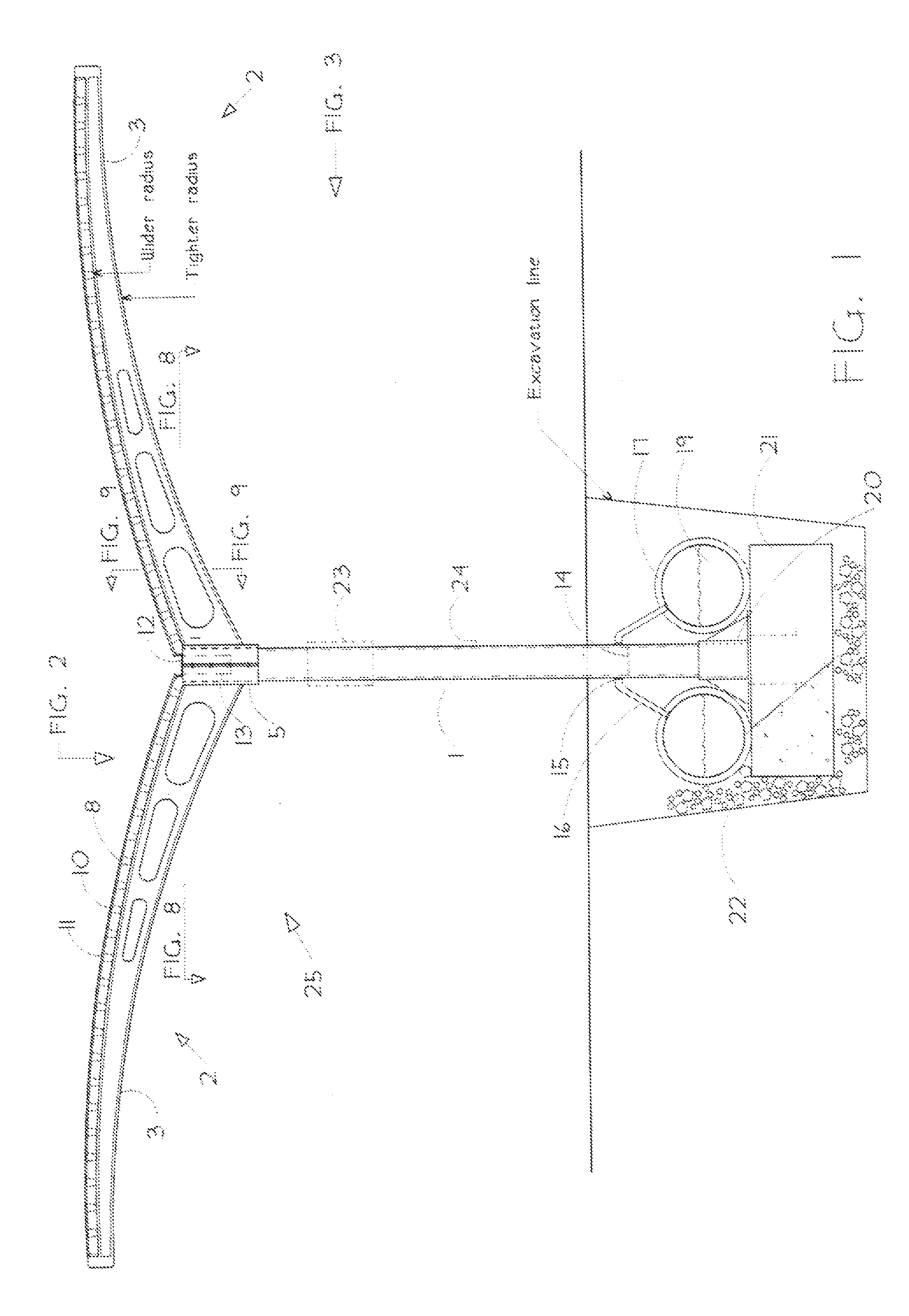
electricity by either photovoltaic film or laminate panels or sheets mounted atop arcuate, curved
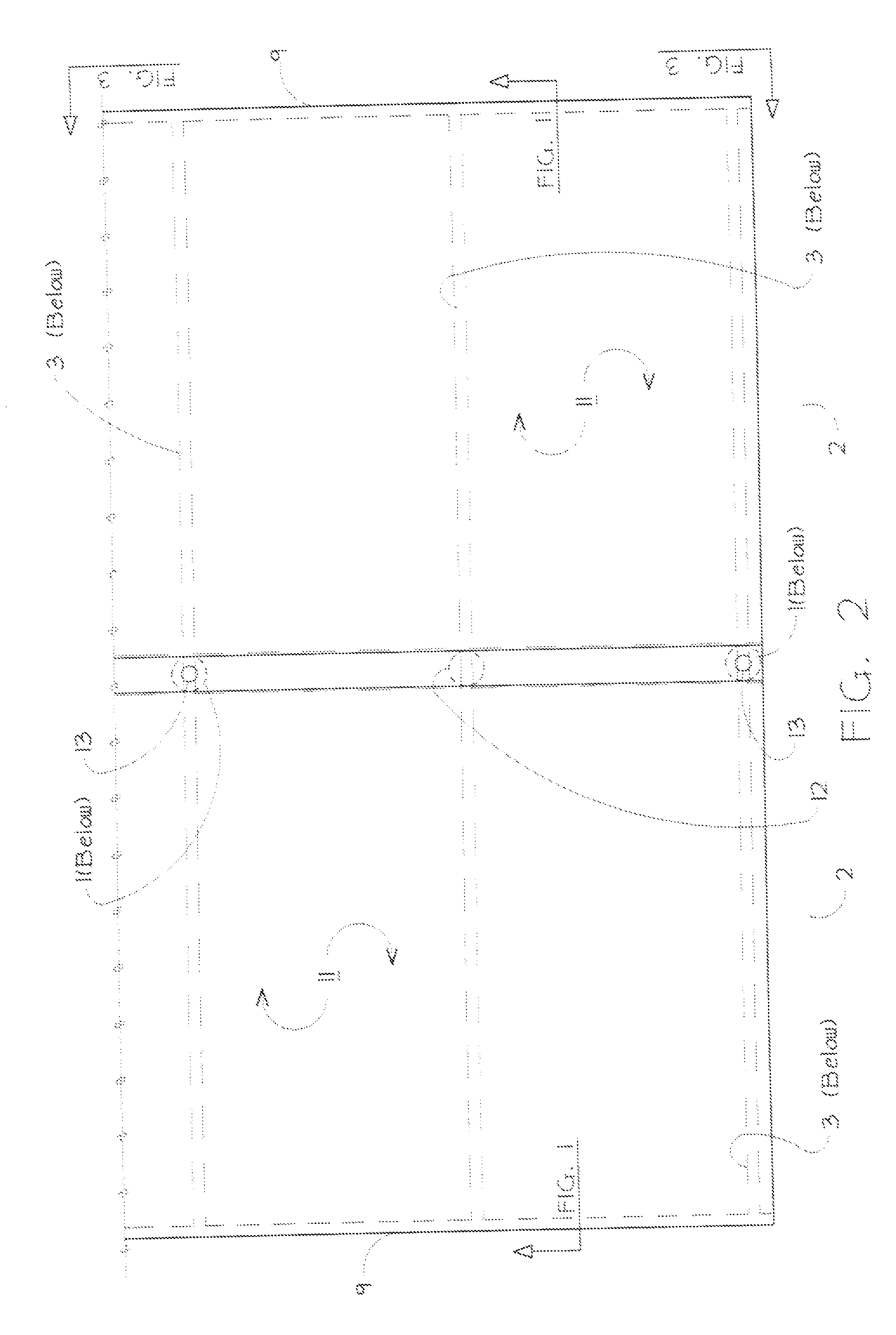
canopy structures that are formed and positioned like “wings”. Rainwater is collected by the low-incidence curved wings and directed to a central trough along the wings' structural spine, which conducts it through a support column to a water container or vessel. In a preferred embodiment the vessel is an underground container extending parallel to and as long as the above-ground structural spine of the assembly. The low-incidence curved wings allow for optimal solar collection (i.e., power production) in mid-day during summer months in the northern latitudes when utilities often experience their highest daily and historic demand. The principal application is for parking lots, as the full canopy assembly provides site and vehicle cooling, and mitigates against
albedo effect for additional environmental benefits. The invention can be used to collect
solar energy, and water from rain or
snowmelt. In addition to parking lots, it can be installed in parks, marinas, walkways, remote areas, and urban areas with adequate
solar access to provide
electricity and store water for later distribution. It further provides a non-polluting,
zero carbon emission method of supplying electricity, and the ability to charge or re-charge electric vehicles or equipment without additional fuel expenditure or supplemental connection to an existing
electrical grid. In it's
parking lot application, it provides shade for vehicles, thereby reducing the need for drivers to run their
air conditioning systems to pre-cool their vehicles prior to driving. In its farm application, it collects water for redistribution, provides electricity to pumps and other farm equipment and provides shelter for
crop, feed, animals and equipment storage. In it's marine application, it may be erected on a
pier and provide grey water for cleaning
watercraft, power for recharging boat batteries and sunshade for
pier users and craft. The arcuate curvature in the winged solar canopy assembly of the invention creates a “
waterfall effect”, such that water moving toward the trough at the proximal edges of the canopy increases in speed due to the curvature and pulls the water at the distal edges of the canopy along with it. This causes the water on the distal edges of the canopy to move faster than water falling on a non-curved canopy. This “sweeping” of the canopy by rainfall assists in the cleaning of the assembly. In addition, the structure and shape of the canopy wing arms allow the edges to vibrate in the wind, which also facilitates the movement of water,
snow and debris off the canopy.

