Gas injection system for etching profile control

a technology of etching profile and injection system, which is applied in the direction of electrical equipment, basic electric elements, electric discharge tubes, etc., can solve the problems of difficult precise control, unsatisfactory cd control effect of temperature control, and remarkable degradation of chip yield of edge parts, etc., to achieve the effect of effectively controlling the cd uniformity or profile of edge parts

Inactive Publication Date: 2011-08-25
DMS CO LTD
View PDF21 Cites 7 Cited by
  • Summary
  • Abstract
  • Description
  • Claims
  • Application Information

AI Technical Summary

Benefits of technology

[0016]An aspect of exemplary embodiments of the present invention is to address at least the problems and/or disadvantages and to provide at least the advantages described below. Accordingly, an aspect of exemplary embodiments of the present invention is t

Problems solved by technology

However, there was a problem that a chip yield of an edge part is remarkably deteriorated because etch rates of a center part and outer part (i.e., edge part) of a wafer are generally different from each other and CD uniformity or profiles are differently formed.
Firstly, regarding controlling a temperature of a wafer, in a case where high power is used as in an oxide film etching process (i.e., an oxide process), a CD control effect due to temperature control is unsatisfied.
Secondly, regarding dividing a showerhead into inner and outer parts or addi

Method used


Image

  • Gas injection system for etching profile control
  • Gas injection system for etching profile control
  • Gas injection system for etching profile control

Examples


Embodiment Construction

[0040]Exemplary embodiments of the present invention will now be described in detail with reference to the annexed drawings. In the following description, a detailed description of known functions and configurations incorporated herein has been omitted for conciseness.

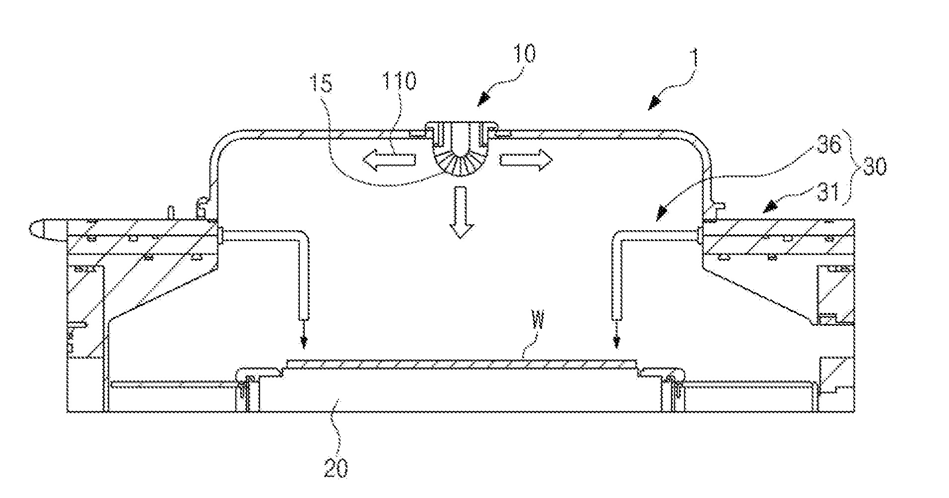
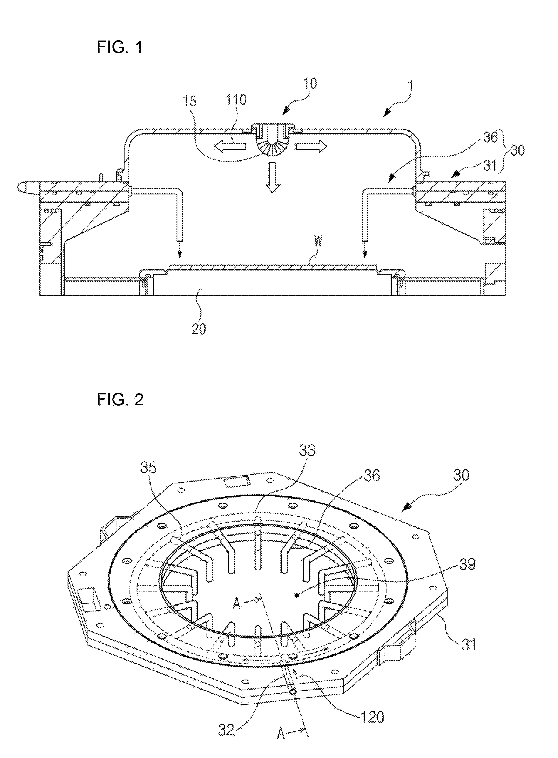
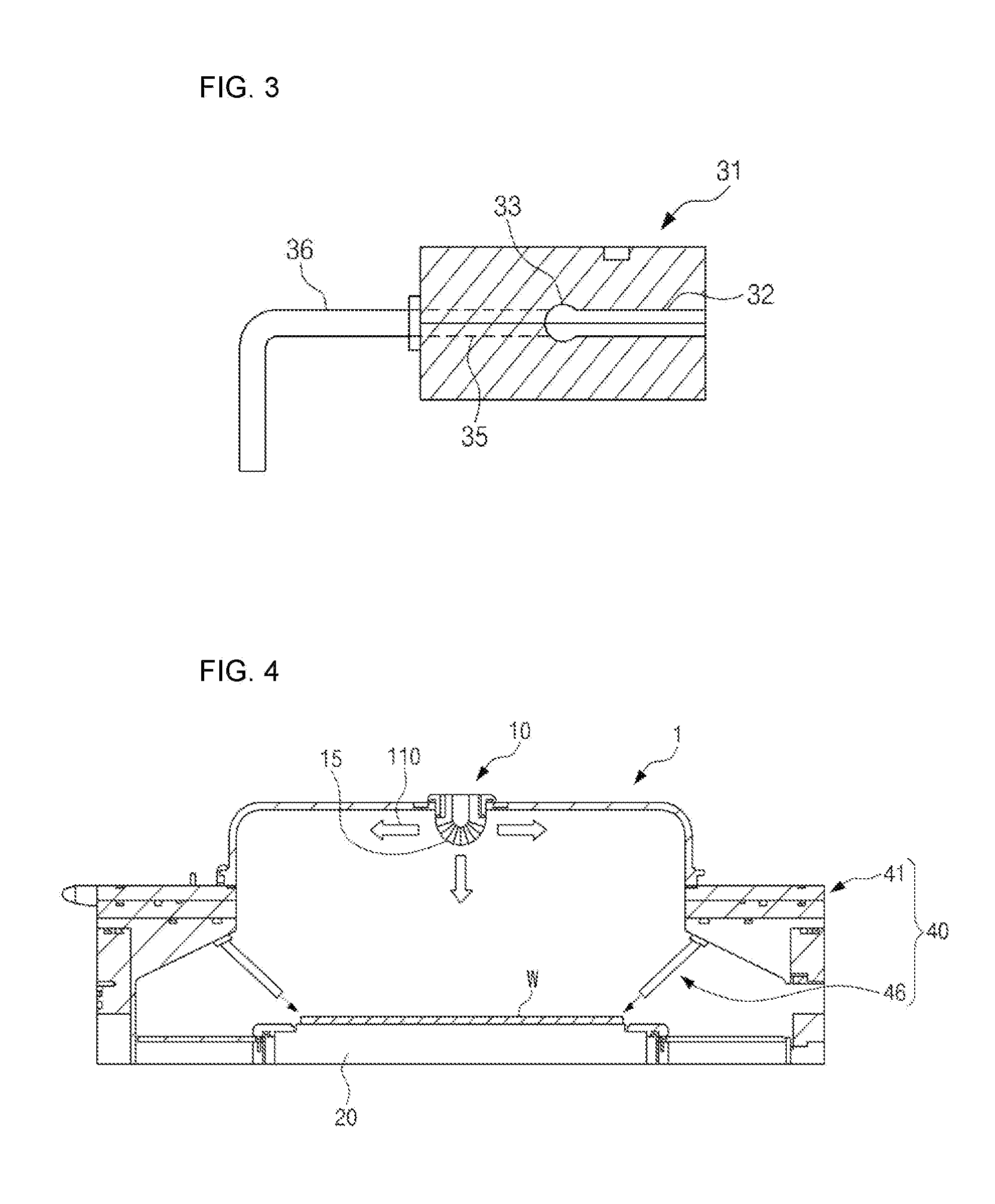
[0041]FIG. 1 is a schematic diagram illustrating a construction of an exemplary embodiment of the present invention. FIG. 2 is a perspective diagram illustrating a side gas injector according to an exemplary embodiment of the present invention. FIG. 3 is a cross section taken along line A-A of FIG. 2.

[0042]As illustrated in FIG. 1, the gas injection system of the present invention includes a top gas injector 10 and a side gas injector 30.

[0043]The top gas injector 10 is installed on a top surface inside a chamber 1, and the side gas injector 30 is installed along a side surface of the chamber 1.

[0044]The chamber 1 is to provide a plasma reaction space isolated from the external in an etching process. The chamber 1 form...


PUM

PropertyMeasurementUnit
Angleaaaaaaaaaa

Abstract

A gas injection system provided in a plasma etching equipment is provided. The system includes a top gas injector for supplying a reaction gas at a top of a chamber, and a side gas injector for supplying a tuning gas from a side surface of the chamber or a backside gas injector upward jetting a tuning gas from a lower side of a wafer. The side gas injector or backside gas injector forms a plurality of jets in a radial shape and simultaneously installs the jets adjacently to an edge part of a wafer such that a tuning gas is jetted adjacently to the edge part of the wafer, thereby being capable of easily controlling a an etch rate or CD uniformity or profile of the edge part.

Description

CROSS REFERENCE[0001]This application claims foreign priority under Paris Convention and 35 U.S.C. §119 to Korean Patent Application No. 10-2010-0015999, filed Feb. 23, 2010 with the Korean Intellectual Property Office.BACKGROUND OF THE INVENTION[0002]1. Field of the Invention[0003]The present invention relates to a gas injection system provided in a plasma etching equipment. More particularly, the present invention relates to a gas injection system for etching profile control, for jetting a tuning gas adjacently to an edge part of a wafer for a user to precisely control an etch rate or a Critical Dimension (CD) uniformity and profile in the edge part, thereby being capable of improving an etching uniformity through uniform formation of a Critical Dimension (CD) and profile of the whole wafer and minimizing a process failure.[0004]2. Description of the Related Art[0005]Generally, an ultra-fine circuit or pattern of a desired is formed on a surface of a large-diameter wafer used for ...

Claims


Application Information

Patent Timeline
IPC IPC(8): C23F1/08
CPCH01J37/3244H01L21/67069H01J37/32449
Inventor SEO, SEONGSULKO, SUNGYONGCHAE, YUNSOOKCHAE, HWANKOOKKIM, KEEHYUNLEE, WEONMOOK
Owner DMS CO LTD
Why Eureka
Try Eureka