
Engineered fuel feed stock

a technology of engineered fuel and feed stock, which is applied in the field of alternative fuels, can solve the problems of increasing the cost of transportation, and increasing the cost of moving engineered fuel feed stock for energy and petrochemical production, and causing significant amounts of pollutants in the gas produced

Active Publication Date: 2011-09-01
REPOWER IP LLC +1
View PDF17 Cites 30 Cited by
  • Summary
  • Abstract
  • Description
  • Claims
  • Application Information

AI Technical Summary

Benefits of technology

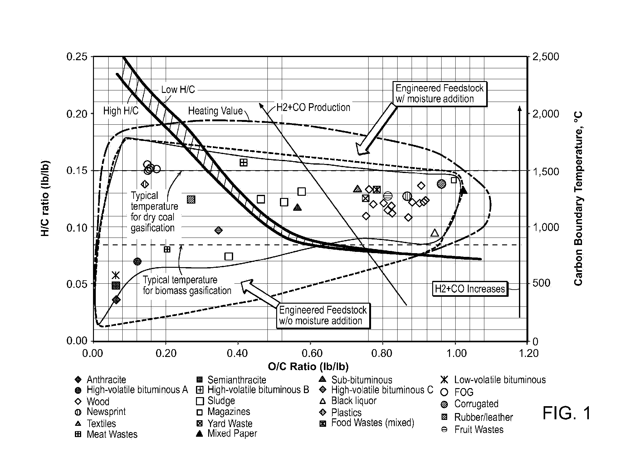
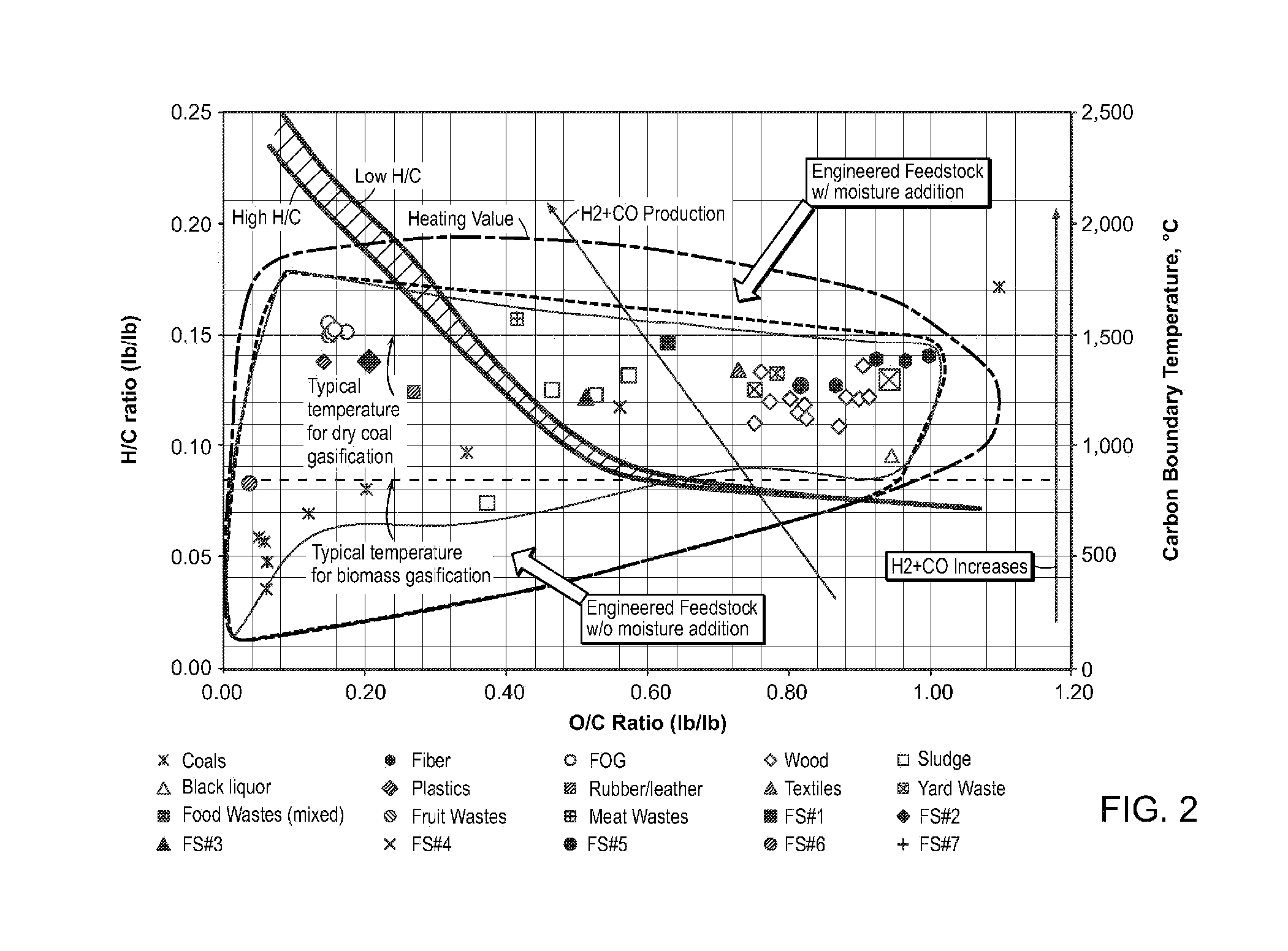
"The present patent describes an engineered fuel feed stock that can be made from a processed MSW waste stream. The feed stock has a unique chemical molecular profile that makes it useful for a variety of purposes such as combustion and gasification. The feed stock can be in the form of loose material, densified cubes, briquettes, pellets, or other suitable shapes and forms. The process involves separating and inventorying the waste streams, which can include recyclable materials and residue. The feed stock has a high heat content, similar to coal, and can be used as a substitute or supplement to coal. It can also produce high-quality syngas for power generation or chemical synthetic applications. The feed stock contains no glass, metal, grit, or noncombustibles, and has a low ash content. The technical effects of this patent include providing an engineered fuel feed stock that can be made from a waste stream and has a unique chemical profile that makes it useful for various applications."

Problems solved by technology

Sources of fossil fuels useful for heating, transportation, and the production of chemicals as well as petrochemicals are becoming increasingly more scarce and costly.
Additionally, due to the ever increasing costs of fossil fuels, transportation costs for moving engineered fuel feed stocks for production of energy and petrochemicals is rapidly escalating.
However, the brute force nature of the combustion of fuel causes significant amounts of pollutants to be generated in the gas produced.
Fine particle pollution from U.S. power plants cuts short the lives of over 30,000 people each year.
The primary disadvantage of updraft gasification is that the synthesis gas contains 10-20% tar by weight, requiring extensive syngas cleanup before engine, turbine or synthesis applications.
The disadvantages of downdraft gasification are that it requires feed drying to a low moisture content (<20%).
For coarse particles, the minimum bubbling velocity and channeling velocity are close or almost equal, but the channeling velocity may be quite different, due to the gas distribution problem.
One potential source for a large amount of feed stock for gasification is waste.
The drawbacks accompanying combustion have been described above, and include the production of pollutants such as nitrogen oxides, sulfur oxide, particulates and products of chlorine that damage the environment.
One of the most significant threats facing the environment today is the release of pollutants and greenhouse gases (GHGs) into the atmosphere through the combustion of fuels.
GHGs such as carbon dioxide, methane, nitrous oxide, water vapor, carbon monoxide, nitrogen oxide, nitrogen dioxide, and ozone, absorb heat from incoming solar radiation but do not allow long-wave radiation to reflect back into space.
Typically, the amount of energy produced per equivalents CO2 expelled during incineration are very low, thus making incineration of MSW for energy production one of the worst offenders in producing GHG released into the atmosphere.
If the replaced material is biogenic (material derived from living organisms), it is not always possible to obtain reductions of emissions.
Materials such as coal, used tires, carpet, and rubber, when combusted, release unacceptable amounts of harmful sulfur- and chlorine-based gases.

Method used

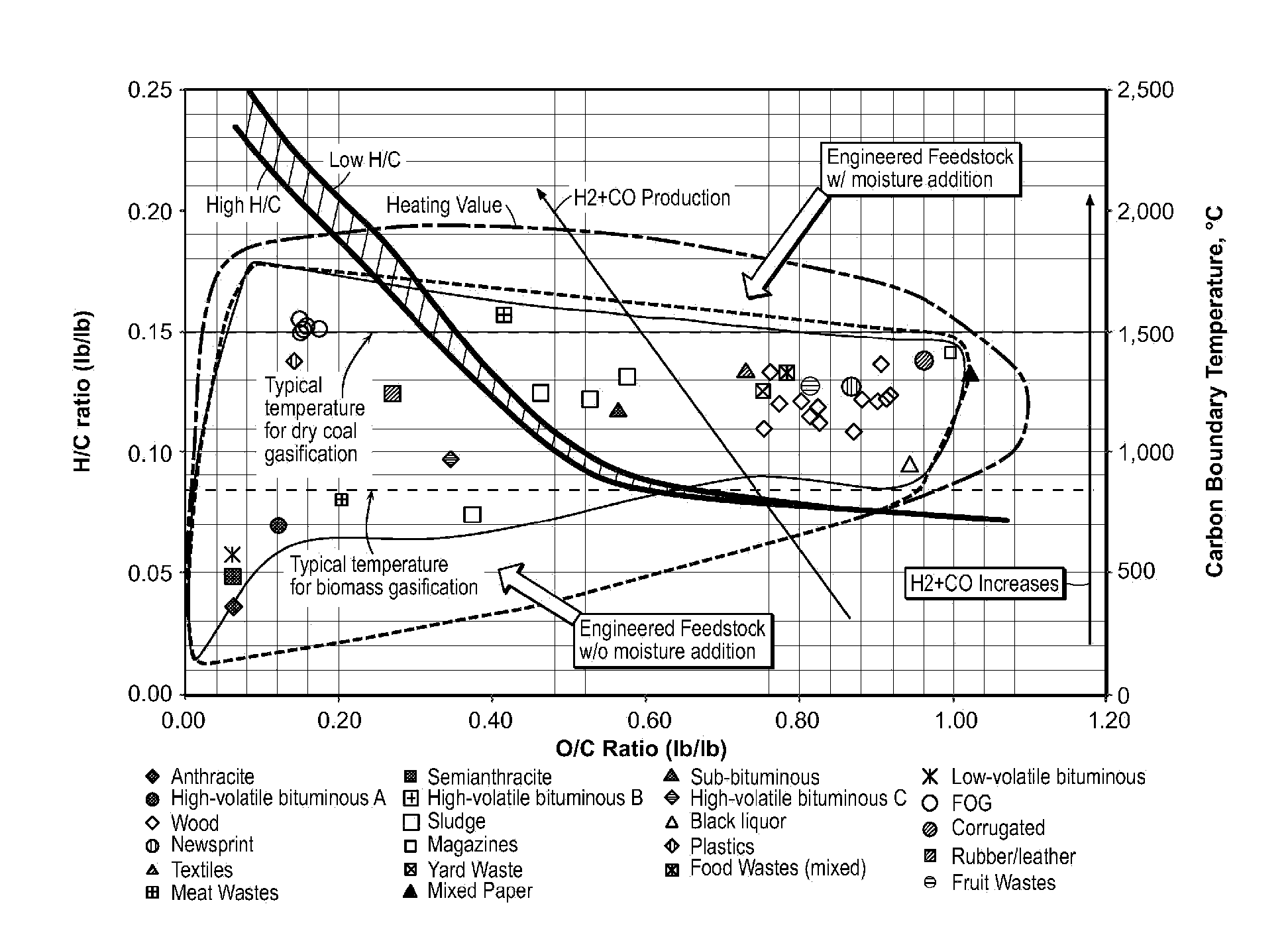

Image

  • Engineered fuel feed stock
  • Engineered fuel feed stock
  • Engineered fuel feed stock

Examples


example 1

[0245]

Test MethodASAIRDRYASTM1 #ParameterRECEIVEDDRIEDBASISD 3302, 5142Total Moisture,21.04——% wtD 5142Residual—7.04—Moisture,% wtD 5142Ash, % wt12.9115.2016.35D 5142Volatile, % wt58.8169.2474.49CalculationFixed Carbon,7.248.529.16% wtTotal100.00100.00100.00D 4239Sulfur %0.180.210.23D 5865HHV Btu / lb108901282113792(Gross)D 3176Hydrogen, % wt4.244.995.37D 3176Carbon, % wt33.8439.8442.86D 3176Nitrogen, % wt0.240.290.31Calculation% Oxygen by27.5532.4234.88difference1American Society for Testing and Materials

example 2

[0246]

Test MethodASAIRDRYASTM1 #ParameterRECEIVEDDRIEDBASISD 3302, 5142Total Moisture,13.26——% wtD 5142Residual—6.09—Moisture,% wtD 5142Ash, % wt14.3915.5816.59D 5142Volatile, % wt63.3368.5773.02CalculationFixed Carbon,9.029.7610.40% wtTotal100.00100.00100.00D 4239Sulfur %0.200.220.23D 5865HHV Btu / lb111651208812872(Gross)D 3176Hydrogen, % wt5.556.016.40D 3176Carbon, % wt41.6845.1248.05D 3176Nitrogen, % wt0.210.230.24Calculation% Oxygen by24.7126.7528.49difference1American Society for Testing and Materials

example 3

[0247]

Test MethodASAIRDRYASTM1 #ParameterRECEIVEDDRIEDBASISD 3302, 5142Total Moisture,15.06——% wtD 5142Residual—4.16—Moisture,% wtD 5142Ash, % wt11.6713.1713.74D 5142Volatile, % wt64.6072.8976.05CalculationFixed Carbon,8.679.7810.21% wtTotal100.00100.00100.00D 4239Sulfur %0.090.110.11D 5865HHV Btu / lb618869827285(Gross)D 3176Hydrogen, % wt4.935.565.80D 3176Carbon, % wt34.9039.3841.09D 3176Nitrogen, % wt0.070.080.08Calculation% Oxygen by33.2837.5539.18differenceD4208Chlorine, % wt0.750.840.881American Society for Testing and Materials


PUM

PropertyMeasurementUnit
temperaturesaaaaaaaaaa
temperatureaaaaaaaaaa

Abstract

Disclosed are novel engineered fuel feed stocks, feed stocks produced by the described processes, and methods of making the fuel feed stocks. Components derived from processed MSW waste streams can be used to make such feed stocks which are substantially free of glass, metals, grit and noncombustibles. These feed stocks are useful for a variety of purposes including as gasification and combustion fuels.

Description

CROSS REFERENCE TO RELATED APPLICATIONS[0001]This application claims the benefit of priority under 35 U.S.C. 119(e) to co-pending U.S. application No. 61 / 076,025, filed on Jun. 26, 2008, and entitled “ENGINEERED FUEL PELLET,” and U.S. application No. 61 / 076,020, filed Jun. 26, 2008, and entitled “ENGINEERED INERT FUEL PELLET,” the disclosures of which are hereby incorporated by reference in their entireties.FIELD OF THE INVENTION[0002]The present invention relates to alternative fuels. In particular, the invention relates to engineering engineered fuel feed stock suited for specific applications including as a fossil fuel substitute for combustion, as well as feed stock for gasification to produce high quality synthesis gas. Feed stock can be engineered to control air emission profiles upon combustion or gasification (such as dioxins, sulfur emitted, as well as others pollutants) as well as to avoid slagging. The feed stock described herein comprises at least one component of proces...

Claims


Application Information

Patent Timeline
Patent Type & Authority Applications(United States)
IPC IPC(8): C10L5/46
CPCC10J3/463C10J2300/0903C10J2300/0909C10J2300/0916C10J2300/0946Y02E50/30C10L5/363C10L5/366C10L5/46Y02E50/10C10L5/36C10L2200/0263C10L2200/0277C10L2200/0295C10L2200/0461C10L5/08C10L5/40C10L5/403C10L5/406C10L5/445C10L2200/0469C10L2250/04C10L2290/24C10L2290/28C10L2290/30Y02E20/18Y02P20/145C01B3/02C10J3/72C10J2300/0906C10J2300/092
Inventor BOHLIG, JAMES W.BAI, DINGRONG
Owner REPOWER IP LLC
Learn More