Medical guide wire assembly

a technology of guide wire and assembly, which is applied in the field of medical guide wire assembly, can solve the problems of limiting the mechanical performance of the guide wire, difficult manufacturing, and affecting the signal transmission of such sensors, and achieve the effect of limiting excessive drive curren

Active Publication Date: 2011-09-01
KONINK PHILIPS ELECTRONICS NV +1
View PDF17 Cites 16 Cited by
  • Summary
  • Abstract
  • Description
  • Claims
  • Application Information

AI Technical Summary

Benefits of technology

[0013]The manufacture is simplified, e.g. it is easier to connect the micro cables to the circuitry chip in that it allows for much easier wire-to-chip bonding, it reduces the number of contact elements in the proximal connector and reduces complexity of wire fabrication. In addition the guide wire tubing that encloses the core wire along the guide wire may then be differently arranged, it could e.g. have a thicker wall.
[0017]A further advantage by this arrangement is that numerous sensors may be arranged along the guide wire as the sensor signals may be transferred simultaneously as they e.g. use different frequency.
[0018]The signalling through the core wire may have both DC and AC components although using only AC components with capacitive coupling has several advantages such as:
[0020]Multiple sensors can readily be used on the same wire.
[0022]“Isolates” capacitive loading from the wire from the signal driver output stage thus limiting excessive drive currents.

Problems solved by technology

Signal transmission from such sensors may be hampered by cable / connector effects, e.g. cable resistance temperature coefficients, contact resistance, leakage due to wetting etc. and bending and mechanical strain on the wire causes disturbances.
If multiple sensors are to be used each sensor requires a separate set of micro cables, and if multiple cable strands and connector elements are used they may severely limit the mechanical performance of a guide wire, and in addition they are difficult to manufacture and are thus prone to reliability issues.

Method used


Image

  • Medical guide wire assembly
  • Medical guide wire assembly
  • Medical guide wire assembly

Examples


first embodiment

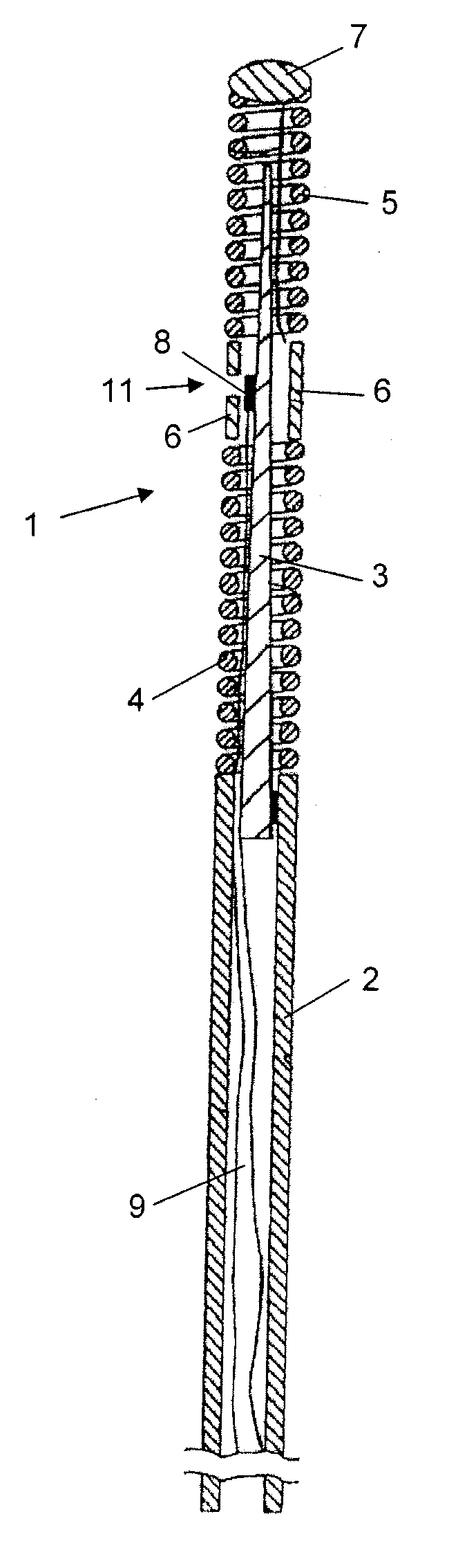
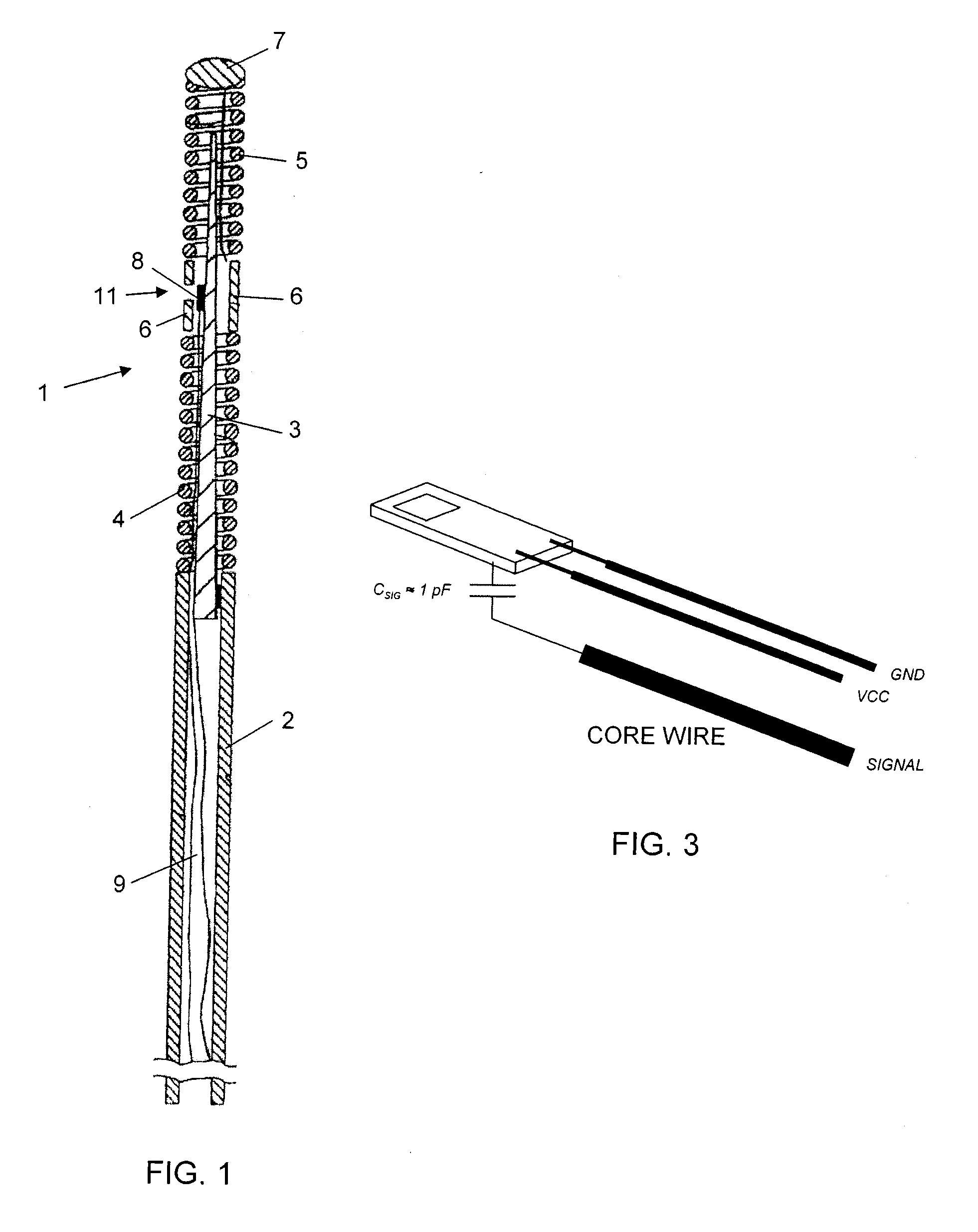
[0041]In the guide wire assembly the core wire is used to transfer the modulated sensor signal, i.e. being the active channel, one of the micro-cables is used for power supply of the circuitry and the other micro-cable is used as ground. This embodiment is illustrated in FIG. 3.

[0042]In order to secure safe signalling an impedance matching circuitry is arranged in the connector housing to take care of impedances between the core wire and the tubing. Two different alternatives are available, in one alternative the core wire is covered at its surface by an insulating layer, e.g. Teflon or a polymer, that may serve two purposes, to electrically isolate the core wire from the tubing and to reduce the friction between the core wire and the tubing. This two alternatives are schematically illustrated in the electrical representations of the guide wire shown in FIGS. 7 and 8, where FIG. 7 shows a so-called floating core wire, i.e. the core wire provided with coating, and FIG. 8 shows a so-c...

second embodiment

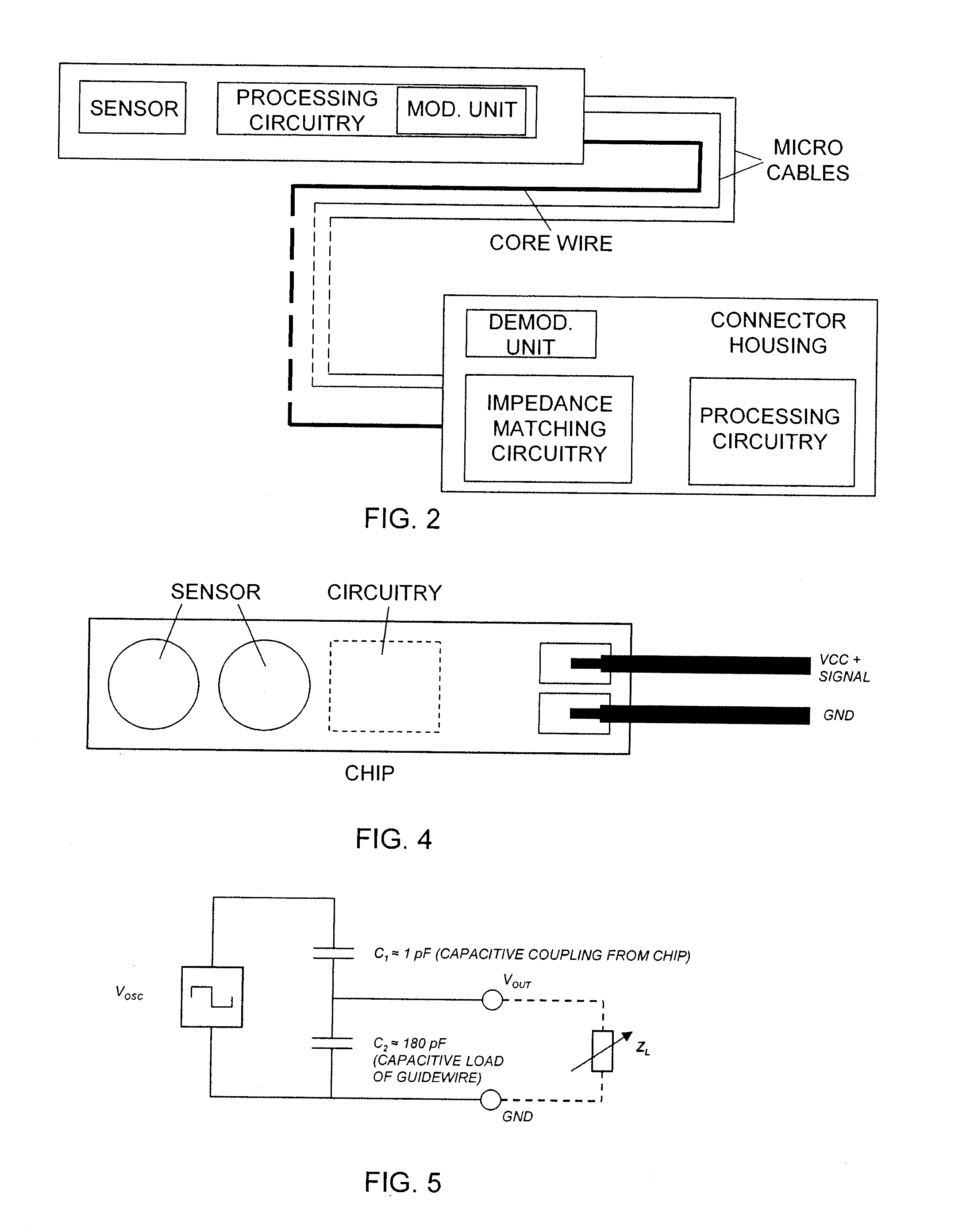
[0046]In the second embodiment, which is illustrated by FIG. 4, one of the micro cables is used as power supply of the sensor chip(s) and for signalling purposes and the other micro cable is used as ground.

[0047]In this embodiment the sensor signal is superimposed on the power supply DC voltage. This embodiment may require large on-chip capacitors (or voltage regulators) at the sensor circuitry chip. The signalling is preferably bidirectional, i.e. both from the sensor and active circuitry to the readout system and vice versa.

[0048]The signalling between the signal processing circuitry and the processing circuitry of the connector housing is performed by the modulated sensor signal which is transferred by using a multiple access technique

[0049]According to three different embodiments the multiple access technique is a frequency division multiple access technique, a time division multiple access technique, or a code division multiple access technique.

[0050]To achieve the modulation, ...


PUM


Abstract

Medical guide wire assembly comprising a guide wire having a proximal end and a distal end, at least one physiology parameter sensor, and that the proximal end of the guide-wire is provided with an elongated connector part, having connection electrodes, for insertion into a connector housing provided with an elongated tubing adapted to achieve electrical and mechanical connection to the elongated connector part, the connector housing is in its turn electrically or wirelessly connectable to a physiology monitor. The guide wire is provided with a core wire running essentially along the entire guide wire. A sensor signal processing circuitry is arranged in connection with the physiological sensor and is adapted to generate a processed sensor signal in response of a sensed parameter. The sensor signal processing circuitry comprises a modulation unit arranged to modulate the processed sensor signal and to generate a modulated sensor signal. The assembly comprises exactly two micro-cables that are connected to the sensor signal processing circuitry, the micro-cables run along the guide wire and are connected to the connection electrodes of the connector part, wherein one of the core wire and the two micro-cables are actively used when transferring the processed and modulated sensor signal to the connector housing.

Description

FIELD OF THE INVENTION[0001]The present invention relates to a medical guide wire assembly according to the preamble of the independent claim.BACKGROUND OF THE INVENTION[0002]The present invention relates generally to sensor and guide wire assemblies, in which one or many sensors is / are mounted preferably at the distal end of a guide wire for intravascular measurements of physiological variables in a living body, and in particular in relation to the communication with the sensor(s).[0003]Sensor and guide wire assemblies in which a sensor is mounted at the distal end of a guide wire are known. In U.S. Pat. No. Re. 35,648, which is assigned to the present assignee, an example of such a sensor and guide wire assembly is disclosed, where a sensor guide comprises a sensor element, an electronic unit, a signal transmitting cable connecting the sensor element to the electronic unit, a flexible tube having the cable and the sensor element disposed therein, a solid metal wire (also called a ...

Claims


Application Information

Patent Timeline
Patent Type & Authority Applications(United States)
IPC IPC(8): A61B5/00
CPCA61B5/6851
Inventor SAMUELSSON, MAGNUSVAN RENS, ANTONIA CORNELIA
Owner KONINK PHILIPS ELECTRONICS NV
Why Eureka
Try Eureka